Ok...caffeine is kicking: eek:
Let be clear about one thing…I'm not an EE...all the good things I've picked up in the last two decades come from a few geniuses in this forum and also to the geniuses they referred to ("the old guys"). So everything I say should be checked...at least twice
In input schematic split resistor R6 in two serial connected resistors (like 2*6k3 /2*6k8 or /2*7k5). Connect R5 top to newly midpoint between resistor (lets call them R6a-R6b). Now you have move your servo injection point completely from signal path. I predict you will be force lower R5 value to something like 10k or even less in order DC servo control to work properly.
Filter signal coming in and out from DC servo opamp...split R24 value in two and build RCRC input filter...do the same to opamp output signal...take 5k1 for R5/R7 value or something like that. As it is, servo opamp is wired as inverting integrator, should work…if not wire opamp as noninverting integrator
Loss C16 feedback cap...it may and probably will induce instability and/or oscillation...Compensation of an CFA should be done elsewhere.
Thank you for suggestions - those were already considered
This kind of servo connection will not work as-is, at the LEDs are rather good voltage references, so the base potentials will not change unless we add resistors in series with the LEDs. The other way of doing it is using 2 additional transistors with their collectors connected to the emitters of those CCSs. Bases of those transistors are grounded, servo drives the emitters. A good option that I use in a much more high-end implementation of the front-end.
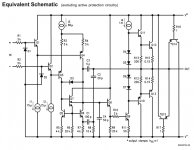
Compensation consists of the lag (C19, C20) and lead (C6) capacitors. This is a good way of compensating a CFA. Employing the current mode amplification, it requires minimal compensation. As you can see at the last (black) picture in post #1, the loop response is very good, stability margins are excellent (phase margin = 84 degrees, gain margin = 24db).
The key requirements I followed designing this amplifier were maximum simplicity and minimum cost (still providing high quality and 100W @ 8 ohm / 200W @ 4 ohm) - most of the solutions used here are well-tested
Quasi OPS is optional - I'm not a fan of quasi arrangements, this one has been done on request of a number of people having lots of IRFP240 and no IRFP9240
No it is not...it is the same quasi output stage found in all Overture series amplifiers like LM3886 and all sisters and brothers. That is the reason why every one is asking: "what that diode doing in the output stage"... it 'not an diode, it is npn transistor which behaves as diode at certain frequency.
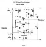
This is LM12CL... it's complementary.
Attachments
No it is not...it is the same quasi output stage found in all Overture series amplifiers like LM3886 and all sisters and brothers. That is the reason why every one is asking: "what that diode doing in the output stage"... it 'not an diode, it is npn transistor which behaves as diode at certain frequency.
LM3886 is a very different story - it uses an interesting combination of a transistor and a diode, working as a level shifter. The driver stage is asymmetric though - rather different from what I use here.
Is 12mA current enough for driving 4 pairs of IRFP ?
Yes, no problem. This is tested in a number of designs.
Despite the fact IRFPs have got relatively high non-linear input capacitance, 12mA is fine.
I have a slightly different OPS design with 5 pairs of IRFP240/9240, driven by MJL0281/0302 at 16.2mA. That one runs and sounds very good in a CFA amplifier.
VHex+ amplifier utilizes the same configuration as the one in Referenz here, but with 2 pairs of IRFP240/9240. Adding 2 more pairs slightly reduces the overall distortion of the OPS, mostly because the class A region becomes wider.
This OPS with 4 pairs has the bandwidth (at -0.5db) slightly above 3MHz, showing THD(1KHz) = 0.09%, THD(20KHz) = 0.12%. Idle current I normally use is around 100mA per pair, although with some good heatsink it can be increased up to, say, 300mA per pair (1.2A in total).
With an appropriate amount of feedback, this thing shows very good performance. I also like it for being stable, robust and inexpensive.
Hi Valery the concept looks very nice but can one pair 1381/3503 drivers can they drive 4 pairs of IRFP240 and 9240s? since the gate capacitance is higher.
Just replied above
At 12mA it drives them fine (local heatsink is required for the drivers for keeping their temperature relatively constant). Expected rails are +/-50...55V DC.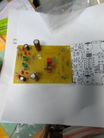
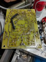
Small progress, but many caps wrong named.
Do you mean - the schematic and the PCB's reference numbers don't match?
Yes,but no problem.Do you mean - the schematic and the PCB's reference numbers don't match?
The problem now is some missing parts...
I have a suggestion for the next version.
Led and transistor(CCS) in thermal contact.
Last edited:
You are super..! im still confused how its possible though..! ksc3503 delivering 12ma at what ambient temperature. Why cant we just stepup with higher capacity transistors? like 2sc5171 or 2sc4793? I believe it can be done though. Any thoughts of mosfets gate protection like adding some zeners in the OPS?Just replied above
At 50V rails, each driver dissipates 12mA * 50V = 600mW, which is fine for TO-126 transistor, equipped with a local heatsink. The drivers run moderately warm, no problem. A big advantage of 3503/1382 - they are very "fast". Those are the Video transistors with fT = 150MHz and low capacitances.
More powerful drivers are normally "slower" - that may require some additional compensation. If you have read my post #47 carefully - I have mentioned there I even used 0381/0302 as drivers. In any case, with the higher fT you will require the lighter compensation and the higher performance.
More powerful drivers are normally "slower" - that may require some additional compensation. If you have read my post #47 carefully - I have mentioned there I even used 0381/0302 as drivers. In any case, with the higher fT you will require the lighter compensation and the higher performance.
- Status
- This old topic is closed. If you want to reopen this topic, contact a moderator using the "Report Post" button.
- Home
- Amplifiers
- Solid State
- Referenz - high-quality low-cost diy-friendly amplifier