square wave.
Attachments

Last edited:
Hi Thimios!
Great job as usual. The front-end looks good, especially considering its overall simplicity - 6 transistors in the signal path 😛
It doesn't seem to indicate any stability issues - in line with the simulated loop response analysis.
It would be interesting to know what you think about the sound. I expect rather accurate reproduction - well, especially with this OPS 😀
Cheers,
Valery
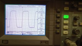
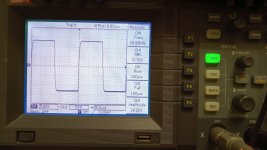
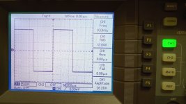
Sorry Jeff no speaker connected yet!
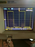
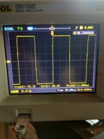
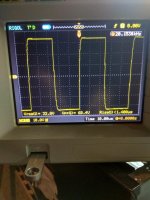
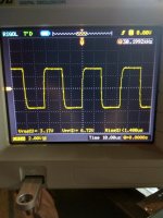
Test patterns first.
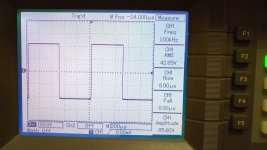
Would you please have a close look at the last pic: What do the sharp edges between the flat and rising/falling parts of the curves mean? May they be interpreted as a sign of oscillation?
Best regards!
Would you please have a close look at the last pic: What do the sharp edges between the flat and rising/falling parts of the curves mean? May they be interpreted as a sign of oscillation?
Best regards!
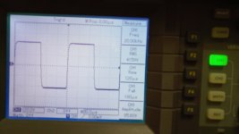
Hi Kay,
The last picture is clipping at 20KHz. What you see is a minor "rail sticking" - after clipping, it takes some time for the clipping elements to come back to linear operation. That's why the signal stays at the clipping level for some longer time than expected and then jumps to the right "position" and continues until it clips on the opposite side of the curve.
There is a number of ways to prevent the rail sticking, however, as this design is meant to be as simple as possible, I have left it "as is" for now, especially since the effect is pretty minor.
Nothing to do with oscillation 😉
Cheers,
Valery
Hi Valery, is it a little overcompensated?
Jeff, is it time for an smd NS compatible version? 😉
Yes, just a little bit, however, it shows around 50V/uS anyway, so I prefer to be on a safe side 😉 If somebody would like to reach perfection in the step response - possible, but it would make sense to perform fine-tuning with particular OPS.
Would it not be possible to use 2 pairs of IRFP260s in the OS, instead of 4 pairs of IRFP240s, to simplify the output stage and the amplifier overall? Thanks.
Would it not be possible to use 2 pairs of IRFP260s in the OS, instead of 4 pairs of IRFP240s, to simplify the output stage and the amplifier overall? Thanks.
Hi Sam,
Two considerations:
1) Input capacitance of IRFP260 is 4 times higher than the one of IRFP240 (power rating is roughly 2x, but capacitance is 4x - not good).
2) Power dissipation from 4 pairs is more efficient than the one from 2 pairs.
In 2017 I and Jeff tried to build the OPS for VHex, based on 800W MOSFETs IXYS (for having some 500W of output power). A specially designed driver stage successfully drove huge input capacitance, however, we have faced a much more serious problem. We could not dissipate the heat from a single pair of outputs.
Answering your question - I prefer 4 pairs at the output 😉
I also like complementary better.
Cheers,
Valery

2nd harmonic being tall and little bit of third will sound good compared to dominant 3rd. Valery for a 4 pair of IRFP240/9240 can we use 2sc5171/1930 as drivers? at about +/-50V? Btw how much current is required to overcome the capacitance of the IRFp240s? Just to calculate it so that there wont be any under estimated load on the drivers.
referenz IMD test.
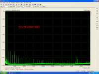
Here are the IMD measurements.
Tested at 30W RMS.
Here are the IMD measurements.
Tested at 30W RMS.
Attachments
Last edited:
2nd harmonic being tall and little bit of third will sound good compared to dominant 3rd. Valery for a 4 pair of IRFP240/9240 can we use 2sc5171/1930 as drivers? at about +/-50V? Btw how much current is required to overcome the capacitance of the IRFp240s? Just to calculate it so that there wont be any under estimated load on the drivers.
Which harmonic is dominant - the 2-nd or the 3-rd - is arguable. What is much more important is the descending profile and low absolute level of distortion.
5171/1930 are very good drivers, although they are not produced anymore as far as I know.
Regarding the driver stage idle current - here is a bit of research.
The output impedance of the driver stage is around 300 Ohm.
The input impedance of 4 pairs of IRFP240/9240 HexFETs:
- at 1KHz: around 500 Kohm;
- at 20KHz: around 25 Kohm.
That means - driving the HetFETs at 1KHz is no problem at all.
Input capacitance comes into play at the higher frequencies, but even at 20KHz the driver's load is still 25Kohm - the load is heavier, but still, nothing to worry about. Open loop swing of the front-end + driver stage at 20 KHz is roughly -6db, comparing to the one at 1 KHz, open loop THD roughly doubles at 20KHz (at 15V RMS: THD1 = 0.022%, THD20 = 0.045%). That means, THD20 with the loop closed will also increase (lower loop gain plus higher open loop distortion), however, it stays pretty low (below 0.01%).
The output impedance of the driver stage is rather weakly dependent on its idle current. However, I wouldn't go lower than 5-6mA. The other point - transistor's fT depends on the output current, coming to its maximum at 10-12mA for 3505/1381 pair.
So - 10-12mA seems to be a "happy medium" for driving a reasonable number of IRFP240/9240 HexFETs (at least up to 5 pairs).
Cheers,
Valery
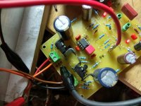
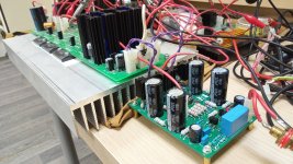
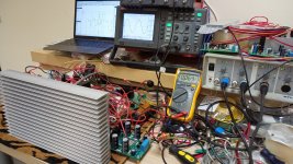
Referenz IPS board prototype - first tests
OK, I have finally got the boards and tested the front-end with my good-old NS OPS early prototype. Running well - I have done some fine-tuning, more details - tomorrow, as well as the full test with Referenz OPS. Excellent IMD performance!
Cheers,
Valery
OK, I have finally got the boards and tested the front-end with my good-old NS OPS early prototype. Running well - I have done some fine-tuning, more details - tomorrow, as well as the full test with Referenz OPS. Excellent IMD performance!
Cheers,
Valery
Attachments
True Valery the harmonic pattern makes bigger difference though but still one grain in the bag.
How did u arrive at the impedance value of 25kohm at 20KHz for the 4 pairs of IRF240s
How did u arrive at the impedance value of 25kohm at 20KHz for the 4 pairs of IRF240s
How did u arrive at the impedance value of 25kohm at 20KHz for the 4 pairs of IRF240s
Just calculated in the simulator.
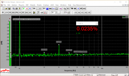
Full Test
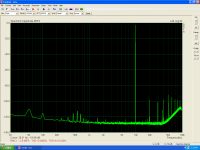
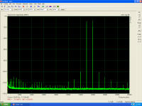
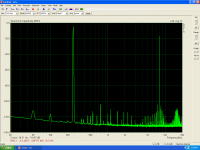
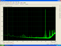
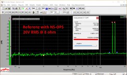
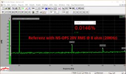
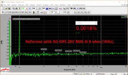
As promised - full test with HexFET OPS.
After a few initial measurements I have increased the drivers' quiescent current up to 15mA. With the heatsink good enough they feel fine. HexFETs are running at 80mA per pair.
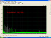
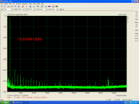
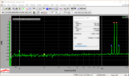
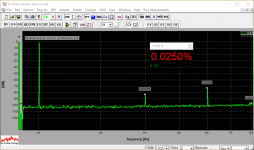
H3 dominance is the specialty of this OPS. What is important - no high-order components in both THD and IMD.
Spectrums are measured at 20V RMS @ 8 ohm.
As promised - full test with HexFET OPS.
After a few initial measurements I have increased the drivers' quiescent current up to 15mA. With the heatsink good enough they feel fine. HexFETs are running at 80mA per pair.
H3 dominance is the specialty of this OPS. What is important - no high-order components in both THD and IMD.
Spectrums are measured at 20V RMS @ 8 ohm.
Attachments
-
 33 Referenz IMD 14-15KHz.PNG49.7 KB · Views: 177
 -
 32 Referenz THD 20KHz.PNG43.9 KB · Views: 188
 -
 32 Referenz THD 01KHz.PNG49 KB · Views: 196
 -
 31 IMG_20190125_174949_1.jpg357.6 KB · Views: 161
 -
 31 IMG_20190125_174949_0.jpg324.8 KB · Views: 150
 -
 31 IMG_20190125_174911_2.jpg341.2 KB · Views: 211
 -
 30 IMG_20190125_175426_4.jpg465.1 KB · Views: 246
 -
 30 IMG_20190125_175411_9.jpg429.2 KB · Views: 238
Referenz 1.3 docs "as built"
Here are the docs based on my live prototype, as built and tested.
PDF images for etching with bigger pads and smaller hole marks are in the archive. I did some tests at the increased ambient temperature, heating up the IPS board with professional dryer - as soon as the temperature increases, the VAS current goes a little bit down (from 6mA to 5.8mA), ensuring safe operation in varying conditions. The drivers require a good local heatsink though.
I also did some listening tests with the shelf speakers in my lab - although I was listening to the single channel, its "character" is rather similar to the one of VHex+, providing the transparent sound with solid bass and lots of details in the mids-highs. Dead silent with no signal. A very fine amplifier.
If assembled correctly - it will work properly at the first power-on. Just set the HexFETs' idle current to 80mA per output pair and readjust after 20-30 minutes warm-up. DC offset is zeroed-out automatically - controlled by a servo.
Some questions - please let me know.
Cheers,
Valery
Attachments
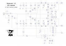
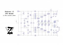
R5=56k(servo out) different connected in this schematic and different in post #20.
What is the right connection?
What is the right connection?
Last edited:
R5=56k(servo out) different connected in this schematic and different in post #20.
What is the right connection?
Thimios, thank you for the observation - this mistake has come back again.
It's connected the right way in the layout though.
I will correct it again. It has to go to the amplifier's input pair.
- Status
- Not open for further replies.
- Home
- Amplifiers
- Solid State
- Referenz - high-quality low-cost diy-friendly amplifier