The input capacitor is low enough value that there's no reason not to use a 35V part.
The feedback caps get hammered worst right around the corner frequency of the input cap, where they see about 1/2 of the input signal. Even with a steady 2Hz signal the amp will be well into clipping by the time a 10V cap sees its 10% guideline.
Still, Naim must have felt less conservative as I believe they used 6V parts there?
A cm or two is ok. But your second regulator schematic (post #67) will be unstable. Even if the simulation doesn't show it.
Turns out the sims do show it, at least on the quasi-complementary side.
The node between the driver and the output device of the CFP is inverted, right? (So it should be greater than 180º, but stay 40º or so short of 360º?)
With the global Miller comp (or with a resistor in series with local Miller comp), it goes past 360º while still above unity gain.

I just had a (perhaps shocking) epiphany: JV's regulators don't use Miller compensation.
I believe he started out with Miller compensation and then played around with it until it worked. But the large resistance he used negates the Miller integrator effect. It does create a big fat zero (as in "poles and zeros", not "something and nothing") around where the gain reaches unity, thereby stabilising the feedback loop.
In fact, if you stop trying to make it Miller compensation and just make it a zero (by connecting the LTP end of the capacitor to ground), you get much better performance.
Have I missed something?
I brushed up on Cordell (again), and he calls this form of compensation "Lag Compensation", and indicates that its main drawback is slew rate limiting.
But I'd still like to know if I've characterised this right, and any thoughts on turning the "pseudo-Miller" zero into a "normal" zero.
But I'd still like to know if I've characterised this right, and any thoughts on turning the "pseudo-Miller" zero into a "normal" zero.
Member
Joined 2009
Paid Member
D. Self looked at compensation through 'loading down the VAS', but I don't think it was seen as better. When you use Cdom (Miller style) you create an a.c. feedback around the VAS device which further linearizes it. I guess you trade off this linearity improvement against the impact on slew rate of the LTP driving this capacitance. I didn't think such slew rate concerns were still a deciding factor, providing the LTP is running enough current and degeneration chosen wisely etc.
Member
Joined 2009
Paid Member
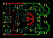
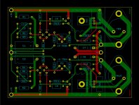
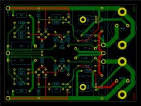
An update on the board designs. Main amp changes are to shorten paths in CFP and to join +/- outputs before feedback take-off point.
Regulators (both Naim and inverted-Naim) also get shorter paths in CFP, along with more compact compensation networks.
Compensation schemes are traditional Naim: Miller + triple lag compensation for amp and Miller/dominant pole hybrid for regulators.
Regulators (both Naim and inverted-Naim) also get shorter paths in CFP, along with more compact compensation networks.
Compensation schemes are traditional Naim: Miller + triple lag compensation for amp and Miller/dominant pole hybrid for regulators.
Attachments
.... You may want to check the pin-outs of your drivers and power transistors.
Well, rats. I thought that worked out a little too well....
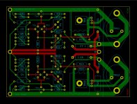
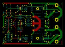
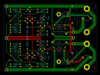
Next iteration:
- fixes the issues regarding TO-3 & TO-126 pinouts @traderbam noticed
- rotates the top TO-3 180º as I got some heatsinks from Les and my guess that the two output devices were in the same orientation turned out to be wrong
- larger I/O holes as I found some swank pin connectors (https://www.mouser.ie/datasheet/2/571/Brochure_MIL-1013710.pdf) to use
Attachments
BC239C avalanche testing
I bought some BC239Cs and ZTX108s from Langrex.
I just avalanche tested the BC239Cs. +V through 33K resistor to collector; emitter to ground.
With bases tied to ground, all of them made it to +86V.
With bases floating, about 1/3 avalanched just above 50V, 1/3 between 50V and 60V, and 1/3 made it past 60V (I didn't run them all the way up to 86V).
This would suggest Naim didn't have to do a whole lot of rejecting -- or I just got lucky.
Please can you share the pdf for home etching?Next iteration:
- fixes the issues regarding TO-3 & TO-126 pinouts @traderbam noticed
- rotates the top TO-3 180º as I got some heatsinks from Les and my guess that the two output devices were in the same orientation turned out to be wrong
- larger I/O holes as I found some swank pin connectors (https://www.mouser.ie/datasheet/2/571/Brochure_MIL-1013710.pdf) to use
Thanks.
@thimios,
I haven't built the boards yet, so I'm hesitant to share a design that might not work. There's one build still in the queue in front of it (a DIY Pass HPA-1), and then I'll be getting stuck in to it.
Once it's built and works, I'll definitely post Kicad files, Gerbers, PDFs, or whatever else folks need.
Cheers,
Jeff.
Thanks Jeff!@thimios,
I haven't built the boards yet, so I'm hesitant to share a design that might not work. There's one build still in the queue in front of it (a DIY Pass HPA-1), and then I'll be getting stuck in to it.
Once it's built and works, I'll definitely post Kicad files, Gerbers, PDFs, or whatever else folks need.
Cheers,
Jeff.
I will wait to see what you will find.
Too many projects on the way, that's mine problem too.

@thimios,
I haven't built the boards yet, so I'm hesitant to share a design that might not work. There's one build still in the queue in front of it (a DIY Pass HPA-1), and then I'll be getting stuck in to it.
Once it's built and works, I'll definitely post Kicad files, Gerbers, PDFs, or whatever else folks need.
Cheers,
Jeff.
Hi Jeff, have you made any progress on this project yet?
thanks
Sajj
- Home
- Amplifiers
- Solid State
- NAP250 clone