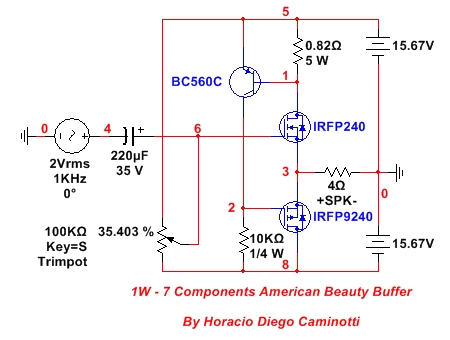
Very simple to build and with outstanding quality parameters. It only requires an adjustment. The output current is properly compensated so as not to expose the output stage to risk.
It should be used with high-performance speakers or it can be used for headphones.
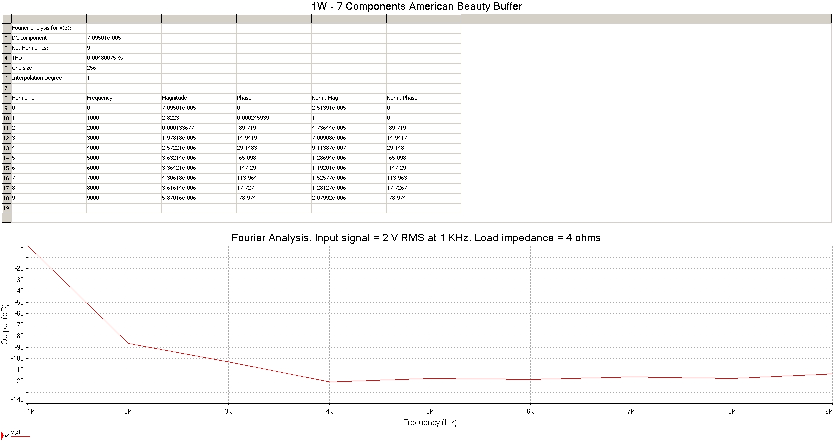
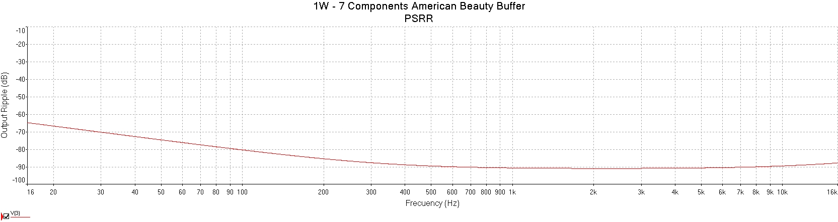
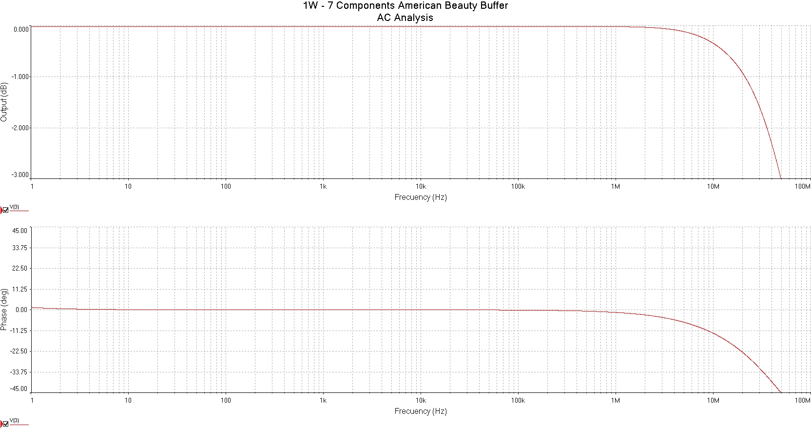
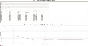
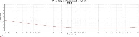
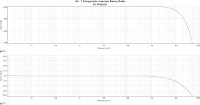
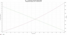
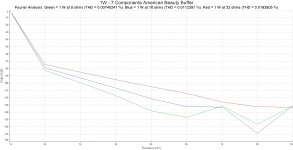
Its outstanding points are: very low distortion and very stable throughout the audible bandwidth, high PSRR
It should be used with high-performance speakers or it can be used for headphones.
Its outstanding points are: very low distortion and very stable throughout the audible bandwidth, high PSRR
Attachments

Attachments

Last edited:
Neat! Do you have FFT and THD plots?
Edit: never mind - I was looking for traditional FFT plots with spikes but yours are connected peaks.
This might be nice headphone amp for even 16ohm headphones.
Edit: never mind - I was looking for traditional FFT plots with spikes but yours are connected peaks.
This might be nice headphone amp for even 16ohm headphones.
Last edited:
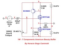
Bias is 600mV/0.82R or about 800mA. Gain is slightly less than unity.
but what intriques me is how you can get the AC current balance equal between the lower and upper MOSFET....?
The way it is drawn now, it is a Single Ended Follower.
but what intriques me is how you can get the AC current balance equal between the lower and upper MOSFET....?
The way it is drawn now, it is a Single Ended Follower.
Hi Horacio,
Yes, perhaps nothing intrigues me more than simple but great sounding circuits. What is the gain and what is the bias current? I might do this with a TO220 MOSFETs for a headphone amp.
Cheers,
X

Being a buffer, its voltage gain is close to 1 (without reaching it by very little).
The bias will depend on the load you wish to connect to the output and under what maximum input voltage you will operate it.
To achieve 1W under 8 ohms, you must circulate a minimum bias of 0.5 A. The 0.82 ohm resistor is responsible for fixing that bias. If you do the calculations, you will see that with it there will be more current than necessary. With a resistor of 1 ohm, in the place of that of 0.82 ohm, it would be enough.
The value of 0.82 ohm would be necessary for a load of 4 ohms at a maximum level of 1 W.
Summarizing:
For 4 ohms => 0.82 ohm 5 W (0.707 A). Max. input voltage = 2 V RMS
For 8 ohms => 1 ohm 3 W (0.5 A). Max. input voltage = 2.828 V RMS
For 16 ohms => 1.5 ohms 2 W (0.354 A). Max. input voltage = 4 V RMS
For 32 ohms => 2.2 ohms 2 W (0.25 A). Max. input voltage = 5.657 V RMS
It is a single ended follower. The supply voltage could be altered to reduce dissipation, if necessary.
Last edited:
but what intriques me is how you can get the AC current balance equal between the lower and upper MOSFET....?
When the current through the 0.82 ohm resistor increases above its static value, under the injection of the positive half-cycle of the input signal, the drain-source conduction of the IRFP9240 is reduced in exactly the opposite way. At the same time, the conduction between drain and source of the IRFP240 is coincident in direction and magnitude with the current of the 0.82 ohm resistor (if the weak current of the base pin of the BC560C is disregarded).
Last edited:
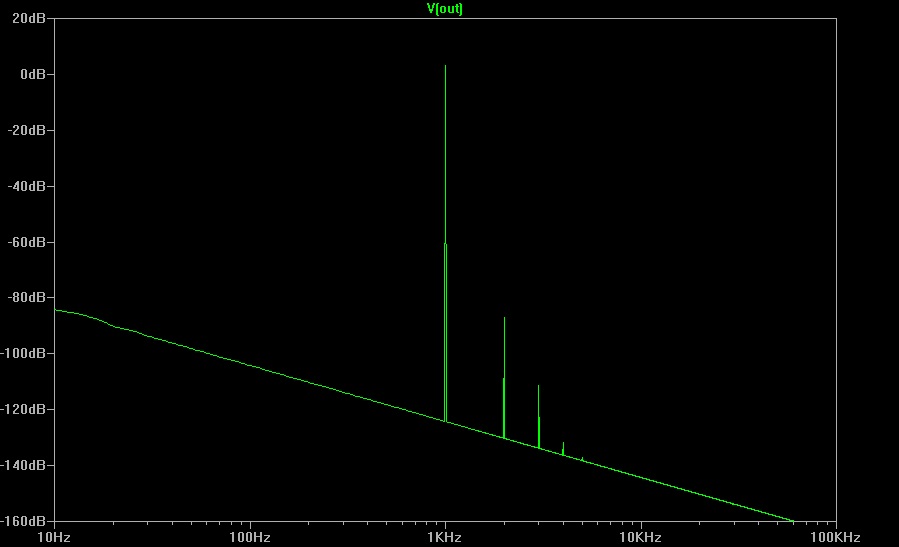
I made the LTspice model for a smaller HPA running 136mA bias and 2W dissipation per MOSFET. Added gate stoppers and a smoothing cap for the bias voltage setpoint. The only thing I found kind of tricky is that the DC offset changes with power supply rail value, and also it changes with bias current setting. My value for 0vdc offset was not the same as Diegomj's value. As a headphone amplifier buffer, it works very well according to the simulation with 0.003%THD driving 4Vpp into 50ohm headphones, and with a very nice harmonic profile. And at a much more reasonable volume of 1Vpp it is 0.00077%THD and still a nice harmonic profile with H2 dominant and very little H3.
Schematic:
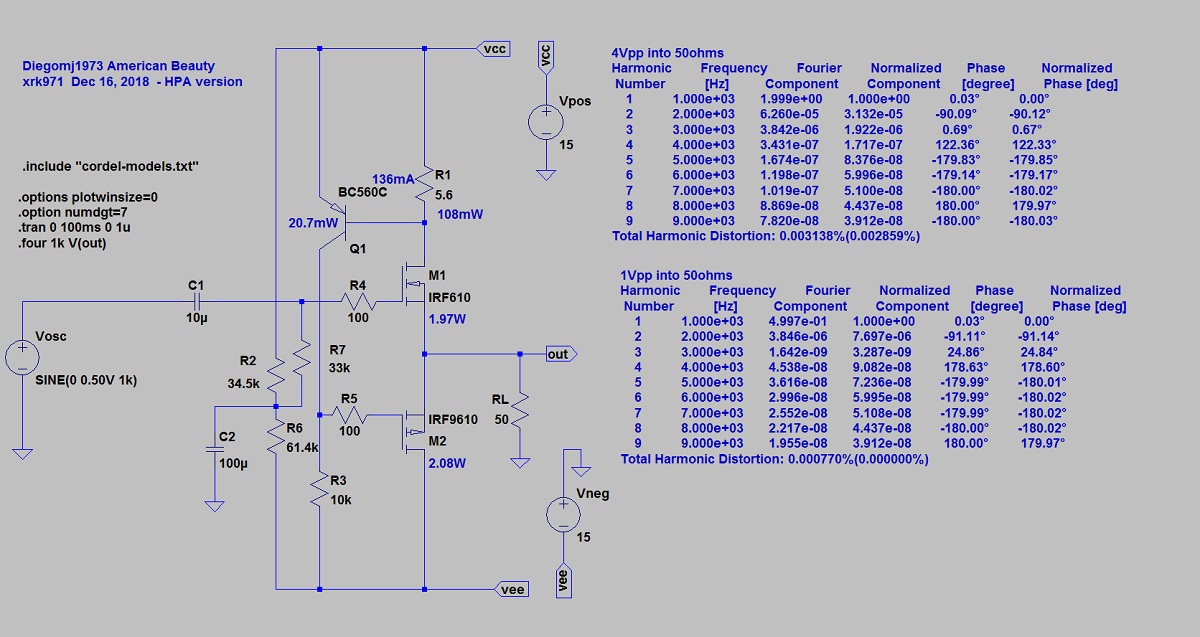
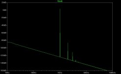
FFT for 4Vpp into 50ohms:

Schematic:
FFT for 4Vpp into 50ohms:
Attachments
Last edited:
Member
Joined 2009
Paid Member
yes.. but the way the 9240 is driven, causes the current across the 0r82 to be constant.
Can we change this into 50% AC current sharing?
Can we change this into 50% AC current sharing?
I still have my doubts about the -PSRR of this thing. Looks like with a constant current going through IRFP240 and BC560C (btw: suggest higher Early voltage part for this one), any -15V ripple would make it across the 10k resistor with little attenuation and get dumped straight into the load. Might be better as a single-supply circuit... +PSRR should be fine.
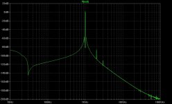
Hint: One would actually be able to see something if you turned on the grid. Also, strongly consider using a decent windowing function, like Kaiser-Bessel.FFT for 4Vpp into 50ohms:
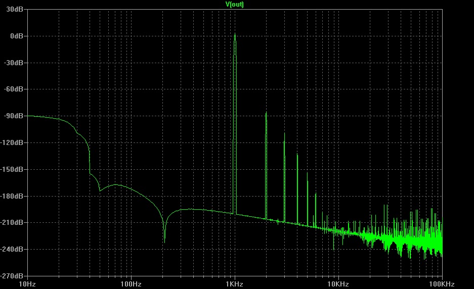
4Vpp into 50ohms, Blackman-Harris window:
Kaiser-Bessel window:
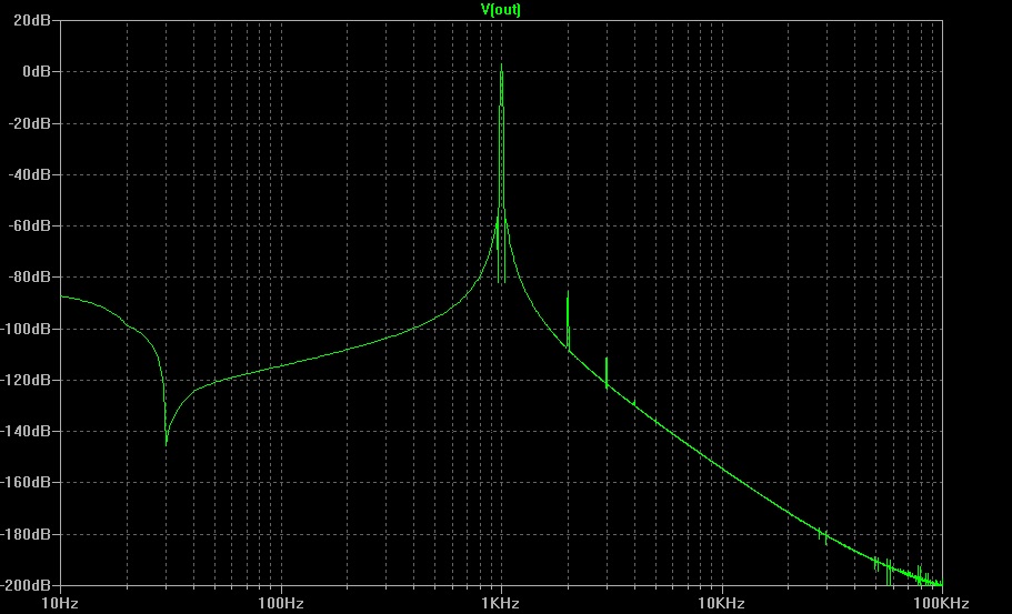
The noise floor on my measurement equipment is -130dB so not sure if any of this matters much vs the standard non-windowed FFT.
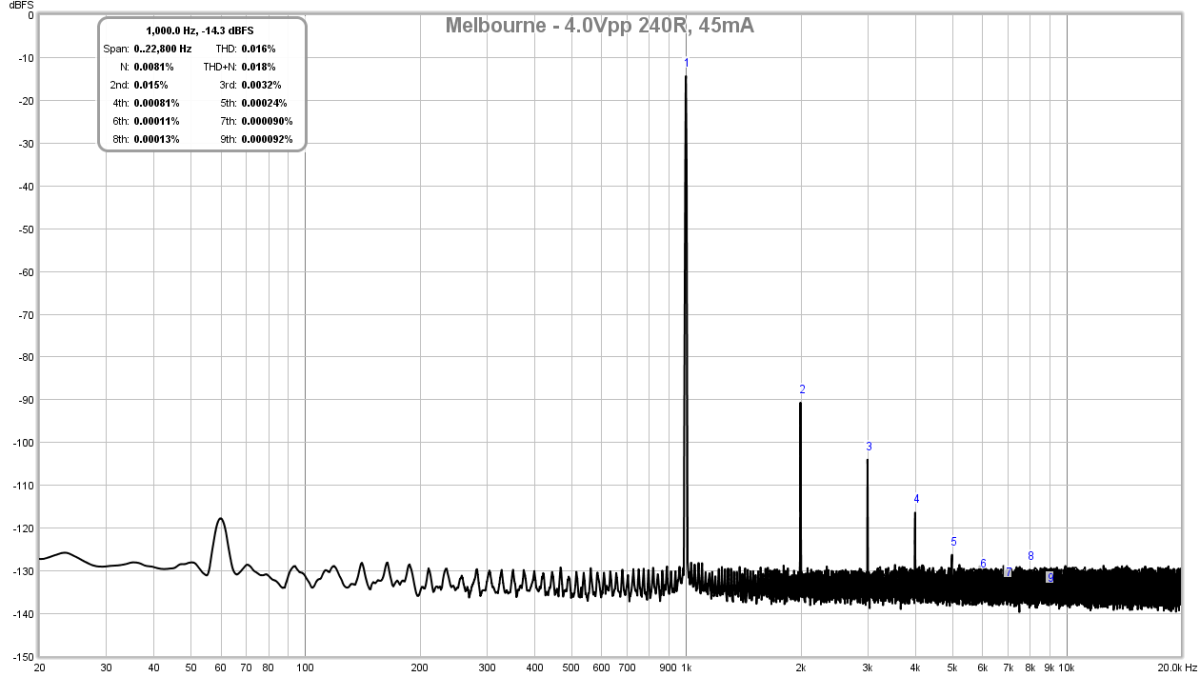
To drive this to any appreciable level will require a preamp, and I would just use my Aksa Lender preamp. But that preamp with beefed up bias current can work pretty well on its own driving 250ohm headphones, albeit with 0.016% THD (but at only 45mA bias current). So I should do a simulation with this as the power amp stage after the Aksa Lender, or even the Melbourne preamp.
Kaiser-Bessel window:
The noise floor on my measurement equipment is -130dB so not sure if any of this matters much vs the standard non-windowed FFT.
To drive this to any appreciable level will require a preamp, and I would just use my Aksa Lender preamp. But that preamp with beefed up bias current can work pretty well on its own driving 250ohm headphones, albeit with 0.016% THD (but at only 45mA bias current). So I should do a simulation with this as the power amp stage after the Aksa Lender, or even the Melbourne preamp.
Attachments

Last edited:
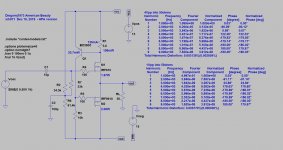
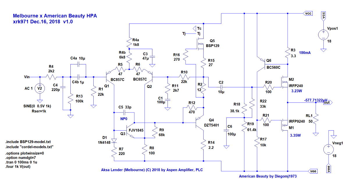
Melbourne X American Beauty HPA
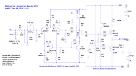
Using the Melbourne as a preamp driving the American Beauty with 186mA bias current and switching to larger IRFP240/9240's for more heat dissipation, I am getting pretty clean results driving 8Vpp into 50ohms.
Schematic:
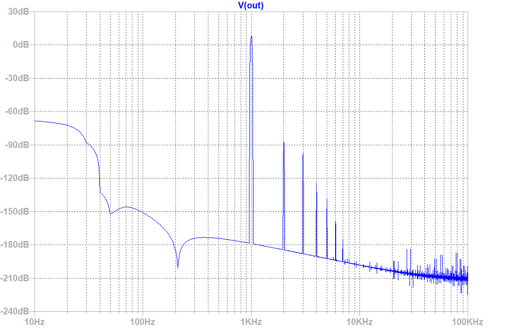
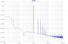
Distortion Components for 8Vpp into 50ohms:
FFT with Blackman-Harris window:
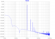
Works well with low impedance headphones too...
Here is 2Vpp into 16ohms:
FFT:

Using the Melbourne as a preamp driving the American Beauty with 186mA bias current and switching to larger IRFP240/9240's for more heat dissipation, I am getting pretty clean results driving 8Vpp into 50ohms.
Schematic:
Distortion Components for 8Vpp into 50ohms:
Code:
Harmonic	Frequency	 Fourier 	Normalized	 Phase  	Normalized
 Number 	  [Hz]   	Component	 Component	[degree]	Phase [deg]
    1   	1.000e+03	3.883e+00	1.000e+00	   -0.15°	    0.00°
    2   	2.000e+03	6.668e-05	1.717e-05	  108.82°	  108.97°
    3   	3.000e+03	1.663e-05	4.284e-06	   11.33°	   11.48°
    4   	4.000e+03	1.791e-06	4.611e-07	  151.80°	  151.95°
    5   	5.000e+03	1.610e-06	4.146e-07	 -177.50°	 -177.35°
    6   	6.000e+03	1.223e-06	3.149e-07	 -179.28°	 -179.13°
    7   	7.000e+03	1.040e-06	2.679e-07	  179.93°	  180.08°
    8   	8.000e+03	9.113e-07	2.347e-07	 -180.00°	 -179.85°
    9   	9.000e+03	8.095e-07	2.084e-07	 -179.98°	 -179.83°
Total Harmonic Distortion: 0.001772%(0.001464%)
FFT with Blackman-Harris window:
Works well with low impedance headphones too...
Here is 2Vpp into 16ohms:
Code:
Harmonic	Frequency	 Fourier 	Normalized	 Phase  	Normalized
 Number 	  [Hz]   	Component	 Component	[degree]	Phase [deg]
    1   	1.000e+03	9.708e-01	1.000e+00	   -0.15°	    0.00°
    2   	2.000e+03	4.974e-06	5.123e-06	  114.47°	  114.62°
    3   	3.000e+03	2.712e-07	2.793e-07	  167.56°	  167.71°
    4   	4.000e+03	4.594e-07	4.732e-07	 -179.41°	 -179.26°
    5   	5.000e+03	3.706e-07	3.817e-07	 -179.93°	 -179.78°
    6   	6.000e+03	3.078e-07	3.170e-07	  179.99°	  180.14°
    7   	7.000e+03	2.636e-07	2.715e-07	 -179.99°	 -179.84°
    8   	8.000e+03	2.306e-07	2.375e-07	 -179.99°	 -179.84°
    9   	9.000e+03	2.048e-07	2.110e-07	 -179.99°	 -179.84°
Total Harmonic Distortion: 0.000519%(0.000000%)
FFT:
Attachments
Last edited:
Diego,
I really like this, it's simple and just like a White Follower with mosfets.
One question:
As the current increases through the upper output, it pulls more current through the 3.3R resistor which in turn drives harder at the gate of the lower output, increasing its current too.
Whilst voltage is set by the upper source follower, the current through the lower device might better work if it reduces as the upper current increases, and vice versa with decreasing current through the upper source follower, the current through the lower resistor should then increase. This would follow the concept of the active CCS in Pass' Aleph J, and it leads to very high efficiency for Class A.
Hugh
current across the upper MOSFET remains constant, the lower MOSFET carriers all the AC current.
It is a true single ended follower, no pushppull action.
It is a true single ended follower, no pushppull action.
I think Hann window is also good, but you need > 8 cycles for a good plot, 16 is better.4Vpp into 50ohms, Blackman-Harris window...
I went ahead and built a TO220 version (albeit with IRF520 and 9520, as they were what I had in my parts bin).
Going to run it through the QA401, and I'll post results when I'm done 🙂

Going to run it through the QA401, and I'll post results when I'm done 🙂
I went ahead and built a TO220 version (albeit with IRF520 and 9520, as they were what I had in my parts bin).
Going to run it through the QA401, and I'll post results when I'm done 🙂
View attachment 722701
Nice, you beat me to it. What voltage and what bias resistor value are you running?
- Home
- Amplifiers
- Solid State
- 1W - 7 Components American Beauty Buffer