A dab of White-out correcting fluid or even white masking tape is better than nothing.
Actually Kapton is quite a good conductor when in thin tape form with silicone adhesive. It’s used in aerospace as radiators. Better is Teflon tape.
Actually Kapton is quite a good conductor when in thin tape form with silicone adhesive. It’s used in aerospace as radiators. Better is Teflon tape.
PS : I forgot to add but the alumina ceramic is very thermally conductive compared to silicone but they aren't terribly reusable, I removed some for remounting on another heatsinks and so far half of them have suddenly split in half
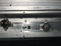
Splitted ceramic is caused by irregular surface of the heatsink, the cure is very simple, lap the mating surface with wet sanding for large area on a thick glass plate.
For small area, or limited access like my attached pictures, I use a lapping stone made out of the ceramic insulator by itself with some cutting compounds.
Attachments
I suspect they were broken during the torque down of the previous use. They are very sensitive to flatness of the mounting surface.PS : I forgot to add but the alumina ceramic is very thermally conductive compared to silicone but they aren't terribly reusable, I removed some for remounting on another heatsinks and so far half of them have suddenly split in half.
I recommend mounting the active devices on a copper spreader using the graphene. Mount the spreader using an insulator. The idea is to spread the heat flux over a larger area first. Directly under the chip, the area used for the thermal flux is essentially the chip dimensions plus the case bottom thickness.
For example, an IR 450 has a chip area of .250 by .250. If the copper bottom is .060 thick, the effective area transferring heat will be .310 by .310. NOT the entire contact area of the package. If you use a bad insulator, then yes the entire package will become a thermal island, but that is not an effective transfer of heat.
By using the graphene to thermally connect to a copper spreader that is .250 thick, you widen the transfer path by the time the heat gets to the bottom of the copper spreader. For the IR450, that makes the area at the insulation .250 plus .060 plus .250, or .560 by 560.
The heat flux density at the insulation is now 1/4 the value it would be without the spreader. If the insulation previously caused a 40 degree rise, it will now give a rise of 10 degrees.
All it costs I height.
jn
I suspect they were broken during the torque down of the previous use. They are very sensitive to flatness of the mounting surface.
I recommend mounting the active devices on a copper spreader using the graphene. Mount the spreader using an insulator. The idea is to spread the heat flux over a larger area first. Directly under the chip, the area used for the thermal flux is essentially the chip dimensions plus the case bottom thickness.
For example, an IR 450 has a chip area of .250 by .250. If the copper bottom is .060 thick, the effective area transferring heat will be .310 by .310. NOT the entire contact area of the package. If you use a bad insulator, then yes the entire package will become a thermal island, but that is not an effective transfer of heat.
By using the graphene to thermally connect to a copper spreader that is .250 thick, you widen the transfer path by the time the heat gets to the bottom of the copper spreader. For the IR450, that makes the area at the insulation .250 plus .060 plus .250, or .560 by 560.
The heat flux density at the insulation is now 1/4 the value it would be without the spreader. If the insulation previously caused a 40 degree rise, it will now give a rise of 10 degrees.
All it costs I height.
jn
Yes, it was due to the uneven torque of the TO3P packages. I'm using a steel bar to apply pressure on the active devices rather than bolt individual ones to apply pressure more evenly.
No, if you're about to use an insulator it defeats the purpose of graphene and graphene does NOT replace thermal paste but what it can be good for is application on the top of plastic packages and SoC cooling etc etc.
Re-read my post. The high conductivity material (graphene) is best suited for the high heat flux density position. As the 45 degree heat cone expands downward, the thermal drop associated with an insulator becomes less and less. Directly under the package surface the heat flux is greatest directly under the chip.
jn
ps.my article in LA #9 does go into this.
I'm not about to support using graphene as a TIM in a high heat flux situation as good thermal paste still performs better even high heat flux density positions and most certainly doesn't cost a bomb.
You could, with that theory first sandwich a FET with graphene with the copper shims then insulate that with alumina ceramic but you might as well use good thermal paste
Last edited:
If one would only consider thermal performance. IMHO there is currently no better practical solution than Keratherm.
Direct mounting on anodised heatsinks without insulator has two problems.
Ordinary anodising is rather thin and the slightest scratch will expose bare aluminium.
The electrical insulation cannot thus be always guaranteed.
Thick hard-anodising may help, but they are quite porous.
SO one needs to find a way to impregnate them with silcone grease or something thermally conductive.
The problem with ceramic insulator is the need for two layers of thermal paste.
According to my analysis in the Linear Audio article, the combined performace is worse than one single thin piece of Keratherm.
The latter does not require thermal paste in between.
But if capacitance to the (usually earthed) heatsink is a problem, then I agree ceramic may be a better choice, as a whole.
One should then try to minimise the impact of the thermal paste.
For example by using those slightly electrically conductive, with a high silver content.
Care should then be taken in applying to avoid unintended short-circuiting.
One more trick we have tried to improve thermal performance is to increase the thermal transfer area.
In our DAO SE headphone amplifier, we solder a larger piece of copper to the small package of the LU1014 power JFET.
The latter then provides a larger heat transfer area for the Keratherm / heatsink.
Patrick
TIM? I'm not sure what that means.I'm not about to support using graphene as a TIM in a high heat flux situation as good thermal paste still performs better even high heat flux density positions and most certainly doesn't cost a bomb.
You could, with that theory first sandwich a FET with graphene with the copper shims then insulate that with alumina ceramic but you might as well use good thermal paste
My experience in this area is um, quite extensive. If you wish assistance, I would be happy to be there.
If you think I've absolutely no understanding of this, that is fine as well..
Don't let the national labs around the planet that I provide guidance to on this stuff sway you. I'm sure you know more than those lab guys. You know, the leading researchers on the planet..
Hey, maybe I can ask you to help me...I'm a relative newbie to this thermal stuff, as I only started in 1981..and have been teaching this stuff to those scientist guys for the last 25 years...
jn
ps..you understand sarcasm, right? Eventually, as you dig deeper into this stuff, you and your "sources" will get back to me....
pps. it takes a lot to disappoint me..congratulations, you have distinguished yourself..
A my wife (who recently passed) would say....I'm done with you.
Last edited:
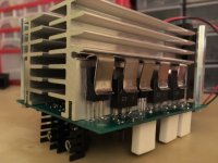
An excellent point.Or use no isolator between the transistors and the heatsink, and isolate the heatsink, like on the picture.
There are separated heatsinks for the npn, and pnp devices.
Sajti
We used to do that back in the 80's with those huge heatsinks that had the 5 inch fan mounted at one end, with 12 to 16 TO-3's mounted. The tunnels were 4 independently isolated aluminum extrusions.
IIRC, didn't QSC use a grounded collector scheme. I remember looking at the schematic and figuring out how it actually worked.
jn
A my wife (who recently passed) would say....I'm done with you.
Very sorry for your loss.
Or use no isolator between the transistors and the heatsink, and isolate the heatsink,
like on the picture. There are separated heatsinks for the npn, and pnp devices.
Still needs thermal paste, though.
JN, can you confirm -
does it goes in this order (from top to bottom)?
Transistor
Graphene
Copper spreader
Thermal paste
Ceramic insulator
Thermal paste
Heatsink
does it goes in this order (from top to bottom)?
Transistor
Graphene
Copper spreader
Thermal paste
Ceramic insulator
Thermal paste
Heatsink
I suspect they were broken during the torque down of the previous use. They are very sensitive to flatness of the mounting surface.
I recommend mounting the active devices on a copper spreader using the graphene. Mount the spreader using an insulator. The idea is to spread the heat flux over a larger area first. Directly under the chip, the area used for the thermal flux is essentially the chip dimensions plus the case bottom thickness.
For example, an IR 450 has a chip area of .250 by .250. If the copper bottom is .060 thick, the effective area transferring heat will be .310 by .310. NOT the entire contact area of the package. If you use a bad insulator, then yes the entire package will become a thermal island, but that is not an effective transfer of heat.
By using the graphene to thermally connect to a copper spreader that is .250 thick, you widen the transfer path by the time the heat gets to the bottom of the copper spreader. For the IR450, that makes the area at the insulation .250 plus .060 plus .250, or .560 by 560.
The heat flux density at the insulation is now 1/4 the value it would be without the spreader. If the insulation previously caused a 40 degree rise, it will now give a rise of 10 degrees.
All it costs I height.
jn
JN, can you confirm -
does it goes in this order (from top to bottom)?
Transistor
Graphene
Copper spreader
Thermal paste
Ceramic insulator
Thermal paste
Heatsink
Yes. on both sides of the copper spreader you should use the most thermally conductive stuff you can find. The best part is you are not limited to insulating material. You could use graphene, copper loaded grease, silver loaded..
By the time you make it to the ceramic insulator, the heat will have spread out sideways enough that the insulating material is not so big a factor. If you choose a non ceramic insulator, you won't take as big a thermal hit once the heat has spread.
I've used copper loaded, but never tried silver. And, I've not used copper loaded for any devices less than about 2 inches diameter.
jn
If one would only consider thermal performance. IMHO there is currently no better practical solution than Keratherm.
Hi Patrick,
Could you please share your reference for Keratherm? None of my usual suppliers seems to carry such an item.
Thanks.
Jacques
Thanks JN. Any specific recommendation for graphene material/product?
Link to a specific product on mouser website (or somewhere else)
would be helpful.
I never tried graphene, and a quick look at "thermal interface" at mouser shows too many options.
I'd like try it in my next amp...
Link to a specific product on mouser website (or somewhere else)
would be helpful.
I never tried graphene, and a quick look at "thermal interface" at mouser shows too many options.
I'd like try it in my next amp...
Yes. on both sides of the copper spreader you should use the most thermally conductive stuff you can find. The best part is you are not limited to insulating material. You could use graphene, copper loaded grease, silver loaded..
By the time you make it to the ceramic insulator, the heat will have spread out sideways enough that the insulating material is not so big a factor. If you choose a non ceramic insulator, you won't take as big a thermal hit once the heat has spread.
I've used copper loaded, but never tried silver. And, I've not used copper loaded for any devices less than about 2 inches diameter.
jn
Thanks JN. Any specific recommendation for graphene material/product?
Link to a specific product on mouser website (or somewhere else)
would be helpful.
I never tried graphene, and a quick look at "thermal interface" at mouser shows too many options.
I'd like try it in my next amp...
No specific recommendation. It's been years since I did it.
I suspect other diy'ers here have purchased recently and could help you. I do recall that back in the day, it was far too expensive for hobby. Hopefully, that has changed.
I've used copper loaded penetrox, but when I look at the site, I can't find a specific heat conductivity number. I'll have to do more looking.
I imagine that CPU applications also have really good thermal conductive loaded pastes, perhaps silver loaded as well (IIRC).
jn
> Could you please share your reference for Keratherm?
> None of my usual suppliers seems to carry such an item.
Keratherm Transistor Insulators – diyAudio Store
Kerafol Thermally Conductive Films from Conrad Electronic International
Patrick
> None of my usual suppliers seems to carry such an item.
Keratherm Transistor Insulators – diyAudio Store
Kerafol Thermally Conductive Films from Conrad Electronic International
Patrick
I'm not sure about specifically the graphene variant but Panasonic's PGS (pyrolytic graphite sheet) which functions quite similar is available at places like Mouser.I never tried graphene, and a quick look at "thermal interface" at mouser shows too many options.
I'd like try it in my next amp...
You can buy the larger sheets and cut them to the size that you need. Most of the sizes are actually prepared for specific IGBT and Thyristor module layouts.
I bought a sheet of their soft PGS to try but didn't get around to trying it due to the lack of insulation.
I tried Sekisui 5760 instead, the performance isn't world class but very good for the dollar. The generic silicone sheets were worse. Downside is that it is a really effective adhesive, the devices needed careful lifting with a scraper after being clamped.
- Status
- Not open for further replies.
- Home
- Amplifiers
- Solid State
- Amplifier heatsink thermal interface experiments