I am aware there is such a thread on the PASS subforum but I am not testing on a PASS amp just a simple 1969 with TIP41 transistors at a measely 500mA bias because the intention for this amp is a bit weird. 😀
Reasoning behind trying multiple thermal interfaces :
1) I saw graphene pads in china so I figured I would find out if it's real
2) Silicon TIM pads and mica is actually quite crap.
3) Aluminium oxide (despite what it sounds like it's actually white) is pricier than both silicon and mica but I am about to find out if it's worth it for a Class A amp
Obviously, a Class A amp will benefit from any form of drop in case temperatures and more efficient case-heatsink thermal transfer.
Also, a similar package FET will have better thermal transfer characteristics than a BJT. Sounds odd, given that both have the same packages but a planar fet is constructed differently from a epitaxial BJT (that would be used most of all in a audio amplifier). Or at least, i know parts like the 2SC5200 has a thermal transfer from die to heatsink of 0.833C/W and a FET like the FQA19N60 is 0.42C/W+0.24C/W and it's not the full fat TO-247 package like the 2SC5200.
I know, it's not a equal comparison but I believe FETs are the way forward. Oh and 2SC5200s are still being made.
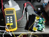
Test conditions : 30c ambient... yeah.. Singapore's an alarmingly hot country.
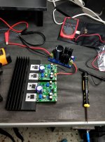
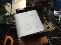
Equipment used :
30V 5A bench supply (I take current readings from the bench supply)
Keysight U1273AX for transistor case temp monitoring (Screen's shot, so I have to use the Bluetooth device to monitor using my phone)
UNI-T UT10A just to measure input voltage from the LT1083
Random dual channel thermometer for taking differential from heatsink to top of case. It was very difficult to keep it attached to the case so the numbers in the photo is not to believed
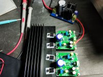
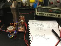
Obviously, anyone who knows anything about the JLH1969 is that the bias goes up or down as the temperature varies and that's also why they blow up when they overheat due to secondary runaway... It takes about half an hour, when the amp was cold it was 0.42A... 30mins later it was 0.63A when I tried to aim for 0.5A bias
I try to maintain 0.4A with all thermal interfaces because that's what I first build the board in this form. And the heatsink stays the same and I also leave the 2nd amp attached but not in operation.
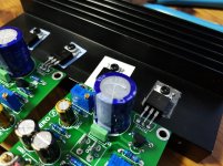
Graphene first up
The graphene sheet actually looks pretty weird. there were no documentations so I guessed that that you only needed to peel one layer off and rejoiced that it was actually non conductive! But I was wrong and had to peel off both layers of protective cover so I left the other thermal material on for the 2nd transistor in case I shorted them out.
Results were already positive, 56c was with silicon pads with a bit of TIM (yes you need that on silicon pads) vs 37c on the graphene
with silicon pads I had 14c temperature differential between the case and the heatsink whereas the graphene I have 2c between them.
The reason for the temperature differential is the extra thermal resistance between the transistor's case and the heatsink that is the insulating silicon pad.
The graphene was genuinely sticky but it was also electrically conductive. So no, you can't use it as a insulating pad...
Oh well.
Using no thermal paste on the silicon pads actually was really bad. 20c temperature differential... Do yourself a favor and use some thermal paste on them.
Moving to aluminium (yes it's written with two i(s) if any yanks are reading this) oxide thermal paste is NEEDED. don't assume it doesn't. and my suggestion is to use decent thermal paste that isn't conductive and certainly not garbage like Arctic Silver 5 or the big tubs of thermal paste that come from china with a crappy spreader with an amazing price.
The case temperature differential is a bit higher this time round, at
5-6c above the heatsink but heatsink still stays cool at 42c.
The amp board is just dissipating 10.5W but that is still a remarkable improvement.
Lessons to take away :
1)If you are using a TO3P package please cover the whole insulating pad with thermal paste but don't overdo it because TO3P doesn't have uniform pressure across the device
2)If you are simply testing or build a cheap amp, silicon is fine (LM3886 amps don't count... they're plastic cases but they still need thermal paste)
Traditional logic that soft thermal pads don't need thermal paste are kinda just fluff. My silicon thermal pads weren't cheap and performed like garbage without thermal paste.
3) A lower case temperature means a smaller heatsink required! But better to keep the same heatsink 😀
4) Graphene is very conductive... I should have known 🙄
5) The more power you put into an amp, the more the temperature differential starts to slide so it will be even more crucial in say... A F5 Turbo V2?
😀
6) Get aluminium oxide pads. Not only do they work even better even though they're thicker than silicon pads but they also are way capable of withstanding way higher voltages.
Reasoning behind trying multiple thermal interfaces :
1) I saw graphene pads in china so I figured I would find out if it's real
2) Silicon TIM pads and mica is actually quite crap.
3) Aluminium oxide (despite what it sounds like it's actually white) is pricier than both silicon and mica but I am about to find out if it's worth it for a Class A amp
Obviously, a Class A amp will benefit from any form of drop in case temperatures and more efficient case-heatsink thermal transfer.
Also, a similar package FET will have better thermal transfer characteristics than a BJT. Sounds odd, given that both have the same packages but a planar fet is constructed differently from a epitaxial BJT (that would be used most of all in a audio amplifier). Or at least, i know parts like the 2SC5200 has a thermal transfer from die to heatsink of 0.833C/W and a FET like the FQA19N60 is 0.42C/W+0.24C/W and it's not the full fat TO-247 package like the 2SC5200.
I know, it's not a equal comparison but I believe FETs are the way forward. Oh and 2SC5200s are still being made.
Test conditions : 30c ambient... yeah.. Singapore's an alarmingly hot country.
Equipment used :
30V 5A bench supply (I take current readings from the bench supply)
Keysight U1273AX for transistor case temp monitoring (Screen's shot, so I have to use the Bluetooth device to monitor using my phone)
UNI-T UT10A just to measure input voltage from the LT1083
Random dual channel thermometer for taking differential from heatsink to top of case. It was very difficult to keep it attached to the case so the numbers in the photo is not to believed
Obviously, anyone who knows anything about the JLH1969 is that the bias goes up or down as the temperature varies and that's also why they blow up when they overheat due to secondary runaway... It takes about half an hour, when the amp was cold it was 0.42A... 30mins later it was 0.63A when I tried to aim for 0.5A bias
I try to maintain 0.4A with all thermal interfaces because that's what I first build the board in this form. And the heatsink stays the same and I also leave the 2nd amp attached but not in operation.
Graphene first up
The graphene sheet actually looks pretty weird. there were no documentations so I guessed that that you only needed to peel one layer off and rejoiced that it was actually non conductive! But I was wrong and had to peel off both layers of protective cover so I left the other thermal material on for the 2nd transistor in case I shorted them out.
Results were already positive, 56c was with silicon pads with a bit of TIM (yes you need that on silicon pads) vs 37c on the graphene
with silicon pads I had 14c temperature differential between the case and the heatsink whereas the graphene I have 2c between them.
The reason for the temperature differential is the extra thermal resistance between the transistor's case and the heatsink that is the insulating silicon pad.
The graphene was genuinely sticky but it was also electrically conductive. So no, you can't use it as a insulating pad...
Oh well.
Using no thermal paste on the silicon pads actually was really bad. 20c temperature differential... Do yourself a favor and use some thermal paste on them.
Moving to aluminium (yes it's written with two i(s) if any yanks are reading this) oxide thermal paste is NEEDED. don't assume it doesn't. and my suggestion is to use decent thermal paste that isn't conductive and certainly not garbage like Arctic Silver 5 or the big tubs of thermal paste that come from china with a crappy spreader with an amazing price.
The case temperature differential is a bit higher this time round, at
5-6c above the heatsink but heatsink still stays cool at 42c.
The amp board is just dissipating 10.5W but that is still a remarkable improvement.
Lessons to take away :
1)If you are using a TO3P package please cover the whole insulating pad with thermal paste but don't overdo it because TO3P doesn't have uniform pressure across the device
2)If you are simply testing or build a cheap amp, silicon is fine (LM3886 amps don't count... they're plastic cases but they still need thermal paste)
Traditional logic that soft thermal pads don't need thermal paste are kinda just fluff. My silicon thermal pads weren't cheap and performed like garbage without thermal paste.
3) A lower case temperature means a smaller heatsink required! But better to keep the same heatsink 😀
4) Graphene is very conductive... I should have known 🙄
5) The more power you put into an amp, the more the temperature differential starts to slide so it will be even more crucial in say... A F5 Turbo V2?
😀
6) Get aluminium oxide pads. Not only do they work even better even though they're thicker than silicon pads but they also are way capable of withstanding way higher voltages.
Attachments
I notice that your heatsinks are anodised. This is quite a good insulator if you are careful not to scratch it. I have made several class A amplifiers by only using a paste under the device. The only problem has been the increased tendency for parasitic oscillations due to the reduce capacitance between an active tab and the grounded heatsink.
I notice that your heatsinks are anodised. This is quite a good insulator if you are careful not to scratch it. I have made several class A amplifiers by only using a paste under the device. The only problem has been the increased tendency for parasitic oscillations due to the reduce capacitance between an active tab and the grounded heatsink.
It's in perfect nick but I found it still conducted electricity on the order of 100ohms. Maybe traditional sense isn't that safe 😱
Suddenly everyone wants to do thermal experiments. 🙂
Experiment: Which mosfet thermal interface material is best?
Patrick
Experiment: Which mosfet thermal interface material is best?
Patrick
And appeared before a few related links :
https://linearaudio.net/sites/linearaudio.net/files/v3 euvl.pdf
https://www.diyaudio.com/forums/pass-labs/37262-mica-goop-6.html#post1032023
Patrick
https://linearaudio.net/sites/linearaudio.net/files/v3 euvl.pdf
https://www.diyaudio.com/forums/pass-labs/37262-mica-goop-6.html#post1032023
Patrick
Usually the tabs (=collectors) of power devices are virtually grounded, too. So, why?The only problem has been the increased tendency for parasitic oscillations due to the reduce capacitance between an active tab and the grounded heatsink.
Best regards!
1. Some MOSFETs have their source connected to the case.Usually the tabs (=collectors) of power devices are virtually grounded, too. So, why?
Best regards!
2. One of my amps has a totem pole of two N-channels.
Usually the tabs (=collectors) of power devices are virtually grounded, too. So, why?
Best regards!
Depends on the output device. As gholl noted, some may not be the same and anyway any capacitance formed may or may not harm the circuit. Years ago, a high speed switcher I built was oscillating and I found the solution by unbolting the heatsink even though it was grounded 😱
After that I put on a insulation pad and it stopped oscillating.
some anodised surfaces are almost perfect insulators some not. And there could a significant nonlinearity in conduction. Resistence may decline with increased voltage and temperature. Be careful!It's in perfect nick but I found it still conducted electricity on the order of 100ohms. Maybe traditional sense isn't that safe 😱
DJDestiny,
if you like, ask Panasonic in Singapore to give you samples of their thermal graphite sheets. There are versions that come with an insulation layer.
if you like, ask Panasonic in Singapore to give you samples of their thermal graphite sheets. There are versions that come with an insulation layer.
The ceramic insulators with thermal paste are about 2x better than the best silicone pads. We use them with the Alpha BB amp which dissipates 100w per big IXYS MOSFET. This is into a 6 heat pipe cpu cooler style sink with fan. IR thermometer shows very cool running body temp of 38C.
+1The ceramic insulators with thermal paste are about 2x better than the best silicone pads...
Very accurate result.
...We use them with the Alpha BB amp which dissipates 100w per big IXYS MOSFET. This is into a 6 heat pipe cpu cooler style sink with fan...
I run 150W with 4 pipes to sink my SIT-3 clone.
Cheers
Attachments
The ceramic insulators with thermal paste are about 2x better than the best silicone pads. We use them with the Alpha BB amp which dissipates 100w per big IXYS MOSFET. This is into a 6 heat pipe cpu cooler style sink with fan. IR thermometer shows very cool running body temp of 38C.
As i noted, obviously I was a bit limited by package dissipation (To220s are puny!) to give an accurate result but I'm building an F5T V2 soon and increased power dissipation will further divide the case temps
Also, IR thermometers aren't necessarily accurate at measuring situations like that.
DJDestiny,
if you like, ask Panasonic in Singapore to give you samples of their thermal graphite sheets. There are versions that come with an insulation layer.
Mine did come with a insulation layer, but it was... no better than silicone TIM with the insulation layer.
I'll check with my friend, he knows someone who can get me graphite sheets 😉
IR thermometers have a problem with shiny metal surfaces. So I stick a piece of Kapton tape onto a metal heatsink to get closer as emissivity of Kapton is about 0.9 vs 0.2 for bare aluminum. The black epoxy body of a MOSFET probably has an emissivity close to 0.9 is my guess. I think the measurement is not too far off. Of course, internal die temp is hotter but only way to get that are internal temp sensors built into the die - like on CPUs.
DJDestiny, Thanks for this.
ON GRAPHENE - are the following comments a fair summary of the conclusions so far ?
i. Awesome without the insulation layer but
ii. Not worth the time and money if it comes with a insulation layer ?
I spent money buying the panasonic insulated graphene sheets but found that keratherm outperformed them. Hence my question...
I have built a dedicated thermal-resistivity-meter:
A Thermal Ohmmeter
And its natural companion:
A Low-Lethality Dielectric Strength Tester
I have also begun to roll my own thermal-contact material:
ELEKTR⚡A is a true High-Voltage lab supply, truly DIY-friendly
(scroll to the end)
A Thermal Ohmmeter
And its natural companion:
A Low-Lethality Dielectric Strength Tester
I have also begun to roll my own thermal-contact material:
ELEKTR⚡A is a true High-Voltage lab supply, truly DIY-friendly
(scroll to the end)
IR thermometers have a problem with shiny metal surfaces. So I stick a piece of Kapton tape onto a metal heatsink to get closer as emissivity of Kapton is about 0.9 vs 0.2 for bare aluminum. The black epoxy body of a MOSFET probably has an emissivity close to 0.9 is my guess. I think the measurement is not too far off. Of course, internal die temp is hotter but only way to get that are internal temp sensors built into the die - like on CPUs.
if you have adjustable emissivity on your IR thermo (I wanted to get one with adjustable emissivity at one point but i decided nah they have their limitations!)
it might work but generally the issue is that kapton isn't exactly a great thermal conductor either.
Another way is to take a TO3P schkotty diode and draw a metric butt ton of current through them and then measure the voltage drop since they vary a lot with voltage rating AND temperature/current 😀
I was about to suggest using a 1969 and measure the current increase but i realize that's not entirely wise as their tempco can vary 😛
DJDestiny, Thanks for this.
ON GRAPHENE - are the following comments a fair summary of the conclusions so far ?
i. Awesome without the insulation layer but
ii. Not worth the time and money if it comes with a insulation layer ?
I spent money buying the panasonic insulated graphene sheets but found that keratherm outperformed them. Hence my question...
Without the insulation layer they are amazing!
With them they are run of the mill even when it's 0.1mm thick... (which mine are)
PS : I forgot to add but the alumina ceramic is very thermally conductive compared to silicone but they aren't terribly reusable, I removed some for remounting on another heatsinks and so far half of them have suddenly split in half
(A certain class AB amp and these 1969s have almost all but shattered with 2 coming from the class AB amp that I am shifting to a much larger heatsink instead of a "puny" 155x40x67 heatsink with a 6.5mm base substrate. Some say they're enough but I like overkill and I'm combining both my Class AB amps one of them a lm3886 amp in a single case with a huge side heatsink for biamping my new bookshelfs)
Last edited:
- Status
- Not open for further replies.
- Home
- Amplifiers
- Solid State
- Amplifier heatsink thermal interface experiments