modification underway
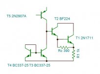
I felt frustrated that the 2n1711 cannot be replaced by any better one . I tried every type of semiconductor even the latest smd mosfets , hopless .So I decided to built a better one by mysef. At this stage the amplifier is still lacking a breeze , on szzzhhh sound the "h" is absent, particularly on female voices . This is due to the reverse c-b capacitance of the driver which is 4pf (bd136 is 30pf). To reduce it, I transformed the transistor into a darlington with an RF transistor , who's reverse capacitance is merely 0.25pf . On simulator the slew rate shoot up by ten fold and the distortion smashed nearly to third and it doesn't need any more roll-off capacitor . R1 flew away.
The two transistors will be mounted together with a 1/8w resistor on a seperate miniature board and replace the driver .The RF transistor is bf224 , it exist since 1965 , used in TV in IF section , widely available at tiny cost.
The 1henry inductor on the bootstrap , the Hammond 158SA is suitable . It has 40 ohm resistance , so it replaces the pull up resistor . It cost at Hawk 6.40$ and about 9$ at Mouser.
Attachments
Well, I just imagined your circuit with no capacitors.Who uses the current of the speaker?
modification underway
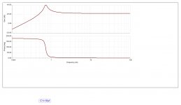
If I chose the JLH1969 amp ,I was 100% sure that it is a well cooked since 50 years by the chefs . I realize how I was wrong . Now I am struggling with the output stage to discover how bad it is designed . First I asked why it is biased 1.2A where 0.8A is necessary for 10w/8ohm . Another question is why JLH who tried a Texas Instrument transistor instead of Motorola , didn't try the 2n3055 very famous at that time .The answer I got when measuring the power bandwidth . The JLH gets at 9w 70khz , but with 2n3055 at 30khz on simulator is shown bellow . In order to have it running up to 70khz I must over bias it to 3A . As you notice on the graph the problem is in the upper transistor that I name it the co-pilot is not fast enough to follow the captain the ,lower one . As the transistors work each on different configuration and diffrent requirements ,why use the same transistor ? The co-pilot needs a faster but as low beta as the captain , I think by this the 2sd388 that Pioneer used in its best amplifiers . Looking for it, I found the 2sd424 is more easiy to find as it has been used in many prestigious amplifiers . So I will use this transistor unless you can advise me other ones , may be this transistor will need less than 250ohm shunting resistance which can eliminate the use of 1henry inductor. Only my ears can tell the issue . As it takes several weeks to tune , I can post the definitive version not before early January .
If I chose the JLH1969 amp ,I was 100% sure that it is a well cooked since 50 years by the chefs . I realize how I was wrong . Now I am struggling with the output stage to discover how bad it is designed . First I asked why it is biased 1.2A where 0.8A is necessary for 10w/8ohm . Another question is why JLH who tried a Texas Instrument transistor instead of Motorola , didn't try the 2n3055 very famous at that time .The answer I got when measuring the power bandwidth . The JLH gets at 9w 70khz , but with 2n3055 at 30khz on simulator is shown bellow . In order to have it running up to 70khz I must over bias it to 3A . As you notice on the graph the problem is in the upper transistor that I name it the co-pilot is not fast enough to follow the captain the ,lower one . As the transistors work each on different configuration and diffrent requirements ,why use the same transistor ? The co-pilot needs a faster but as low beta as the captain , I think by this the 2sd388 that Pioneer used in its best amplifiers . Looking for it, I found the 2sd424 is more easiy to find as it has been used in many prestigious amplifiers . So I will use this transistor unless you can advise me other ones , may be this transistor will need less than 250ohm shunting resistance which can eliminate the use of 1henry inductor. Only my ears can tell the issue . As it takes several weeks to tune , I can post the definitive version not before early January .
Attachments
how bad it is designed.
I'm waiting for your final version to find out.
I think it is well known from experience with early NAD amplifier models, that 2N3055 was a very different hometaxial transistor made by RCA, in the 1960's. The modern, Motorola spec. type is epitaxial, with quite different frequency characteristics. Probably, JLH was aware of this and looked elsewhere for suitable power transistors, even in 1969.....Another question is why JLH who tried a Texas Instrument transistor instead of Motorola , didn't try the 2n3055 very famous at that time ....
https://en.wikipedia.org/wiki/2N3055
I've answered this several times in various threads. It is because the old style transistor technology (hometaxial and epi base) exhibits a variation in gain in collector current which falls considerably from a high of over 100 at about 200mA to 20-something at 4A. In the JLH, the base current to the output transistors is shared, so the peak base current needed has to be divided by 2 in the quiescent condition. As the quiescent current is then lower than the peak, the gain is higher, so the quiescent current is higher.First I asked why it is biased 1.2A where 0.8A is necessary for 10w/8ohm .
This situation is not the case for the linear-gain "ring emitter" or whatever manufacturers call them, which should be able to operate much closer to the ideal current.
Unfortunately, quasi-saturation also takes a hit on the output power, so the modern transistors may need higher Vcc to give a low distortion full power output.
I like the idea of your current mirror to boost the gain in the JLH, with one side as a "dummy" current to allow the operating current in the PNP input transistor to increase. I used exactly this idea many years ago in a single ended, capacitor coupled amplifier which is used as a general purpose amp, or variac for curve tracing now. It was necessary to use this to avoid what would have been a very high value resistor or low currents when the next stage is a Darlington-like VAS. (I hesitate to call the dual NPN VAS a Darlington as critics complain that the collectors are not connected).
Your idea of a choke is something I think JLH would have approved of. The problem here in the UK is that the supply of readily available audio grade EI laminations is disappearing, and toroidals are really out of the question for hand winding. Also, gapped toroidal iron cores are uncommon, still, though are now available.
While JLH discussed using a choke output stage, a choke in the driver is a fascinating idea.
I'm wondering whether a single output transistor with an output choke would be of interest. I keep looking at this idea but each time, the choke costs are high and the circuit does not benefit from cancellation of even harmonics. But perhaps that would not be an issue, after all, many liked the SE 300B design...
Your simulations raise the question of what models you are using. I don't know if there were ever any SPICE models generated for the original (RCA) 2N3055 (these predated SPICE) from the manufacturer. I had to build my own. In which case a modern 2N3055 (epi base) would be very similar to the older TI transistors, and would not be represented by models for the old 3055.
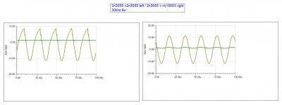
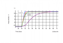
Some time ago I posted this comparison (or a similar one) (buried in the JLH 10W thread somewhere, I think, a few years back) of output transistors. This shows a risetime for an old 2N3055H, a new 2N3055 which is similar to the 2N3716 and the MJL3281A outputs. Your comment about the driver Cjc is interesting, but one of my investigations into the JLH led me to conclude that the new high speed devices would be better.
I am surprised that you think the 2N1711 would be better than the BD139. The RCA datasheet shows Cjc(max) of 25pF (at 10V) compared with 25pF (from the BD135 model) which will be quoted at 0V.
I am surprised that you think the 2N1711 would be better than the BD139. The RCA datasheet shows Cjc(max) of 25pF (at 10V) compared with 25pF (from the BD135 model) which will be quoted at 0V.
Attachments
Last edited:
Thank you anti for your proposition . The D533 look very interesting with beta up to 200 and Ft 8Mhz . But searching on line to buy , It looks to be an extinct specie as is the case for BDY 55/56. On the other hand it is intended for switching amplifiers .
My heart beats for D338 , It has Cob of only 190pf vs 300pf for the D424 . Its Ft falls to 6Mhz at 1A vs 5Mhz at 2A for the D424. For this I will develope for both transistors and leave the option to the diy to choose . The D424 seams to be still manufactured and can be bought on Ali for 2$ a piece and by unity , where as the D338 must be purchased with its compliment and sometimes by several pairs.
The adventage of using higher beta on the co-pilot , It can be lowered at will to equate that of the captain , by using very low shunting resistor of few ohms. This allows the diy to adjust precisely by measuring the ac current on PS to go minimum . As the shunting resistor becomes so low than the pull up resistor with higher value ,doesn't need any more inductor , but the bootstrap capacitor needs to be 10000uf of very low voltage .
The D338 is triple diffused mesa vs probably Epitaxial as most Toshiba D424. Can someone describe the out coming difference of the two technologies?
Last edited:
The 2n3055 spice model I use is
*Si 115W 70V 15A 20kHz pkg:TO-3 3,2,1
.MODEL 2N3055 NPN(IS=4.66E-12 BF=360 VAF=100 IKF=0.25 ISE=3.339E-11
+ BR=2 ISC=5E-9 RB=3 IRB=0.001 RBM=0.4 RC=0.04 CJE=5.802E-10 VJE=1.2
+ MJE=0.45 TF=8E-8 XTF=1 ITF=3 PTF=120 CJC=2.121E-10 MJC=0.4 TR=2.55E-6
+ XTB=1 )
Another one which must be parametric ,as it needs a missing number on line four, probably the beta is
* Pin Assign: 1=Collector 2=Base 3=Emitter
.SUBCKT 2N3055 1 2 3
Q1 1 2 3 3 2N3055_BJT
.MODEL 2N3055_BJT NPN(
+IS=2.37E-8 ISE=1E-9
+ISC=1E-9 XTI=3
+ BF=73 BR=2.66 IKF=0.8 IKF=0.4 XTB=1.5
+ VAF=90 VAR=30 VJE=0.65 VJC=0.65
+ RE=0.00856 RC=0.0856 RB=0.81
+ CJE=415E-12 CJC=1000E-12 XCJC=0.75 FC=0.5
+ NF=1 NR=1 NE=1.26 NC=1.5 MJE=0.5 MJC=0.33
+ TF=100E-9 TR=0.51E-6
+ EG=1.11 KF=1E-9 AF=1
+ VCEO=60 ICRATING=10 MFG=STMICRO)
The Motorola specs for 2n1711 gives Cobo of 4pf and Ft of 300Mhz typical.The bd 135 on Siemens specs give typical Ft 90Mhz at 50ma , forgot where I saw Cob 30pf.
To my opinion JLH is over biased 1.2A so that by using MJ480 it can achieve the power bandwidth .If he had to use the 2n3055 he needed to over bias at 3A to get the same result. Once I will mismatch the transistors I will try to adjust it at lower bias if I get a better sound .
Sorry It is not 2sd338 but 2sd388.
Last edited:
Thanks for posting the 2N3055 models. The first one shows tf=80ns which is quite slow (2MHz) and would seem not to meet the stated "epi spec" of 2.5MHz (min). while the second one shows 100ns which could well be related to the old RCA type device (1.6MHz) as Thomson, I believe, built 2N3055's (and other devices) under licence from RCA in the old days.
I would have expected the tf for modern devices to be better. Time for another look at some actual devices - add that to the "to do" list.
I would point out that the MJ480 also had a high gain variation with current which needed the higher quiescent current as I explained. (Spec. gives 50 @ 50mA, 30 @1A, 10@3A (minimums).
It is not surprising that different manufacturers have different performance in their transistors.
What matters is whether you can still get the devices and whether they actually have the performance expected, as manufacturers have often moved their production lines around as companies are bought and sold.
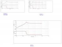
The particularity of 2n3055 that it has a Fhfe that I have seen on RCA datasheet and can be seen also on Siemens one, to be >10khz only . The model I am using positions it at 20khz ,you can see it on the output impedance curve . As the co-pilot is driven by current , the 20khz limit is the active one not the Ft.
http://www.alldatasheet.com/datasheet-pdf/pdf/44083/SIEMENS/2N3055.html
http://www.alldatasheet.com/datasheet-pdf/pdf/44083/SIEMENS/2N3055.html
The problem is that neither RCA nor Siemens nor Motorola manufacture the 2N3055 you are modelling today. These companies have all gone or changed hands. Infineon, which came from the semiconductor arm of Siemens, do not appear to sell discrete BJT's; they do list MOSFETS and IC's of various descriptions; ON Semiconductor came from Motorola but only sell the epi-base device, and RCA have in the meantime gone. ST, too, recently obsoleted their 2N3055 along with most or all of the old metal can devices.
As Ian mentioned, the latest 2N3055's have higher fT than the old types, and indeed I have reported fhfe's of 50-60kHz, so could I recommend that you update your models rather than continuing with the old ones?
However, one well known manufacturer's models are not great. I've complained and not had a good response, which is surprising as designers use modelling almost without exception and bad models do not encourage good design. The model this company provided is datasheet worst case, and my point is that it would only apply to perhaps 1% of devices if that, and then perhaps not all specs. at the same time.
In another thread I made the point that manufacturers' models should reflect current typical performance, even if the spec. remains the same. Otherwise we keep having to measure and reinvent wheels all the time. ST sell a TIP3055 which is a similar epi base device so perhaps a model for that from ST (or Power Innovations if they still have a model - they emerged as the discrete arm from TI it would appear) might be worth tracking down if you cannot make your own.
Last edited:
- Status
- This old topic is closed. If you want to reopen this topic, contact a moderator using the "Report Post" button.
- Home
- Amplifiers
- Solid State
- sublimed JLH1969