Huggygood , s'il vous plait , do me a favor. Take three 2n3055 Motorola and others if possible and measure with standard digital multi meter , the capacitances c-b and b-e , and post the values .
ok,i do that ,but not today 🙂
I have a lot of work and little time for my hobbies.
I will start with the biggest brands.
I have a lot of work and little time for my hobbies.
I will start with the biggest brands.
I suspect your Motorola 2N3055's from 2000 will not be the ones you have the models for, but at least one generation newer epi base.
I'm not sure what you mean about "grey leads". Early devices used solder plated leads with, I understand, ordinary leaded solder. These are normally quite bright but tarnish especially if stored in damp conditions. Maybe if the kit is from China and these devices have been stored a while (somewhere) they will have tarnished a little. The newer "G" lead-free leads are slightly brighter. Early Motorola power transistors were packaged in aluminium cans.
I'm not sure what you mean about "grey leads". Early devices used solder plated leads with, I understand, ordinary leaded solder. These are normally quite bright but tarnish especially if stored in damp conditions. Maybe if the kit is from China and these devices have been stored a while (somewhere) they will have tarnished a little. The newer "G" lead-free leads are slightly brighter. Early Motorola power transistors were packaged in aluminium cans.
...you are right. Just found an aluminium can Motorola 2N3055 in the "archives". Its leads were gold(plated).
Huggygood , s'il vous plait , do me a favor. Take three 2n3055 Motorola and others if possible and measure with standard digital multi meter , the capacitances c-b and b-e , and post the values .
I have measure 3 pieces motorola aluminium.
One measure 4pf be and 2pf bc.
Two measure 2pf be and 2pf bc. same series number.
Measured using LCR Hameg meter.
Last edited:
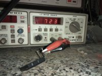
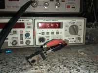
Sorry for this but the right is 4nf&2nf!Thank you thimos , when I measure 2sc5200 , I get c-b 300pf and b-e 1.4nf .
Now TTC5200 is be=5.5nf bc=
720pf.
Again sorry!
Attachments
Last edited:
The final
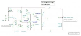
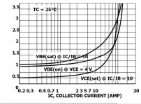
The 2n3055 is a living dinosaur of obsolete technlogy . It has a very particular character that only those who have seen the RCA datasheet know about , the Vbe/Ic function . If a voltage is varied on the base in common emitter ,the base current increases exponentionlly . If the Hfe remains constant , than the Ic increases also exponentially . The 2n3055 has the Hfe parameter bearish above 300ma which linearises the exponential Ic , yielding very linear Vbe/Ic function above 500ma . This is why my ears were asking the base resistor of the driver to be very low to drive the lower output in voltage mode . Motorola came up with a different version , the 2n3055A /mj15015 which has the Hfe bearish at lower current, making the Vbe/Ic more linear from 0.2-2.2 amps . Replacing the 2n3055 withmj15015 gave the amplifier higher headroom ,more dynamic .
The driver to be low impedance I replaced the bjt with a mosfet of very high transconductance ssm3k339 . It is SMD component of little cost but needs a piece of pc board 5mm x10mm, slot by scalpel a T shape and a hole to screw on a small heat sink. At 25ma it is 2.5 ohms source impedance and revere capacitance of 7pf only . The frequency responce of the couple 3k339/mj15015 is 14khz . At this frequency the upper output must provide 40% extra current by having at least 50% higher Hfe , on condition that itself has much higher frequency responce . At high frequencies than the lower becomes a constant current sink letting the upper work in single ended . The driver's current which follows that of the base emitter diode is bullish , to compensate , the upper output which acts inversely must also have bullish Hfe . To resume , the upper output transistor must be of high Hfe of high Ft and bullish Hfe but of TO3 casing. The transistor I chose is 2sc2489 . It has an Ft of 100Mhz and provides service here up to 1Mhz . It cost 5$ on line from ebay Toshiba version including shipment ,but from shop in Bangkok it cost about 2$ . Now the total frequency responce of the driver + output group exceeds the Mhz ,to form a dominant pole in order to apply a high NFB ratio, I added a feedback capasitor of 10pf from output to driver's gate , it is similar to integrator in op amp . The gate resistor now adjusts both the pole and the open loop gain at the same time , allowing it to tune the sound by trading off the open loop frequency responce and the distortion number.
The input transistor is also replaced by the compliment of the driver , ssm3j327 . It requires about 8 ma to have the same transconductance of the replacing transistor . The 8.2k pull up resistor of the CCS is lowered to 3.3k and the pull up resistor 3.9k replaced by two 3.3k in parallel . The mosfet transistors have ruler strait varying transconctance , that is they generate exclusivley even order harmonics . The gate resistance of the driver I set to 4.7k to have an open loop responce of 20khz , but after listening several days I noticed that after 2-3 hours of listening the music was no more interesting . I paralleled the 4.7k with a 10k to higher fr to 30khz, and the music remaind all time exciting , although instantly I cound hear no any difference .
The open loop gain now is more than ten times the precedent version . The mosfet driver provided more punch , higher presence . The input mosfet made the sound more airy , The 2sc2489 enchained the strangled high frequencies to have flying piano notes . The frequency responce at 1 watt was still flat at 1Mhz .
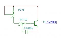
Adjustment is done by adding with wires externally a 1k adjust and the 100ohm adjust from the kit , see circuit bellow . Adjust first the center operating point of 13.5volt with KT1 ,adjust the 1k to have 1.25A bias current . Apply a music and adjust the 100ohm to get the maximum bass . My Floating Single Ssupply technique works only when the two outputs are complimentary ,as the upper has to be higher Hfe at DC , with AC, the shunt resistor decreases the Hfe to be equalized . Measure the resistance values from the center of 100ohms to the base and the resistance from the same center to the collector and apply fix resistors in KT1 and R8 . The value of bootstrap capacitor depends upon the shunt resistor KT1 . To adjust the value eider have inversly proportion to my values or by listening . If low value is used as 220uf the bass becomes loose , "boo"ing , generates headache after listening few minutes , whereas higher values as 6800uf makes too emphasized bass, head hammering dongs , dirty cellos as a PA amplifier does . Once the value is determined after few days of listening replace it with audio quality type , as the input 100uf capacitor. The voltages of these capacitors are only few volts ,maximum 25v is suitable.
The high impedance of the input mosfet , this amp can receive 10k volume pot.
Warning: The mosfets are very sensitive to static electricity . Unplug the unisolated sodering iron when dealing with them aswell as the input capacitor. I destroyed a pair by inadvertence while trying out different input capacitors.
Thank you for your patience.
Kokoriantz
The 2n3055 is a living dinosaur of obsolete technlogy . It has a very particular character that only those who have seen the RCA datasheet know about , the Vbe/Ic function . If a voltage is varied on the base in common emitter ,the base current increases exponentionlly . If the Hfe remains constant , than the Ic increases also exponentially . The 2n3055 has the Hfe parameter bearish above 300ma which linearises the exponential Ic , yielding very linear Vbe/Ic function above 500ma . This is why my ears were asking the base resistor of the driver to be very low to drive the lower output in voltage mode . Motorola came up with a different version , the 2n3055A /mj15015 which has the Hfe bearish at lower current, making the Vbe/Ic more linear from 0.2-2.2 amps . Replacing the 2n3055 withmj15015 gave the amplifier higher headroom ,more dynamic .
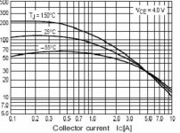
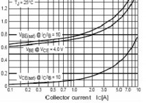
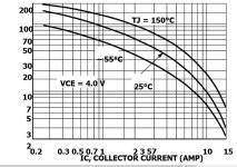
The driver to be low impedance I replaced the bjt with a mosfet of very high transconductance ssm3k339 . It is SMD component of little cost but needs a piece of pc board 5mm x10mm, slot by scalpel a T shape and a hole to screw on a small heat sink. At 25ma it is 2.5 ohms source impedance and revere capacitance of 7pf only . The frequency responce of the couple 3k339/mj15015 is 14khz . At this frequency the upper output must provide 40% extra current by having at least 50% higher Hfe , on condition that itself has much higher frequency responce . At high frequencies than the lower becomes a constant current sink letting the upper work in single ended . The driver's current which follows that of the base emitter diode is bullish , to compensate , the upper output which acts inversely must also have bullish Hfe . To resume , the upper output transistor must be of high Hfe of high Ft and bullish Hfe but of TO3 casing. The transistor I chose is 2sc2489 . It has an Ft of 100Mhz and provides service here up to 1Mhz . It cost 5$ on line from ebay Toshiba version including shipment ,but from shop in Bangkok it cost about 2$ . Now the total frequency responce of the driver + output group exceeds the Mhz ,to form a dominant pole in order to apply a high NFB ratio, I added a feedback capasitor of 10pf from output to driver's gate , it is similar to integrator in op amp . The gate resistor now adjusts both the pole and the open loop gain at the same time , allowing it to tune the sound by trading off the open loop frequency responce and the distortion number.
The input transistor is also replaced by the compliment of the driver , ssm3j327 . It requires about 8 ma to have the same transconductance of the replacing transistor . The 8.2k pull up resistor of the CCS is lowered to 3.3k and the pull up resistor 3.9k replaced by two 3.3k in parallel . The mosfet transistors have ruler strait varying transconctance , that is they generate exclusivley even order harmonics . The gate resistance of the driver I set to 4.7k to have an open loop responce of 20khz , but after listening several days I noticed that after 2-3 hours of listening the music was no more interesting . I paralleled the 4.7k with a 10k to higher fr to 30khz, and the music remaind all time exciting , although instantly I cound hear no any difference .
The open loop gain now is more than ten times the precedent version . The mosfet driver provided more punch , higher presence . The input mosfet made the sound more airy , The 2sc2489 enchained the strangled high frequencies to have flying piano notes . The frequency responce at 1 watt was still flat at 1Mhz .
Adjustment is done by adding with wires externally a 1k adjust and the 100ohm adjust from the kit , see circuit bellow . Adjust first the center operating point of 13.5volt with KT1 ,adjust the 1k to have 1.25A bias current . Apply a music and adjust the 100ohm to get the maximum bass . My Floating Single Ssupply technique works only when the two outputs are complimentary ,as the upper has to be higher Hfe at DC , with AC, the shunt resistor decreases the Hfe to be equalized . Measure the resistance values from the center of 100ohms to the base and the resistance from the same center to the collector and apply fix resistors in KT1 and R8 . The value of bootstrap capacitor depends upon the shunt resistor KT1 . To adjust the value eider have inversly proportion to my values or by listening . If low value is used as 220uf the bass becomes loose , "boo"ing , generates headache after listening few minutes , whereas higher values as 6800uf makes too emphasized bass, head hammering dongs , dirty cellos as a PA amplifier does . Once the value is determined after few days of listening replace it with audio quality type , as the input 100uf capacitor. The voltages of these capacitors are only few volts ,maximum 25v is suitable.
The high impedance of the input mosfet , this amp can receive 10k volume pot.
Warning: The mosfets are very sensitive to static electricity . Unplug the unisolated sodering iron when dealing with them aswell as the input capacitor. I destroyed a pair by inadvertence while trying out different input capacitors.
Thank you for your patience.
Kokoriantz
Attachments

Huggygood , s'il vous plait , do me a favor. Take three 2n3055 Motorola and others if possible and measure with standard digital multi meter , the capacitances c-b and b-e , and post the values .
I have not forgotten you, but I have too much work in the workshop and I do not have time to do that right now. however, be sure that I will do it.
Hello Kokorianz, i have tried some of your mods and have to subscribe to your findings. Indeed, your mods do increase the sound quality reproduction and takes it to another level.. I have to report that i have tried replacing the 140ohm resitor with 100ohm coil here: JLH 10 Watt class A amplifier.Forget it , the project has achieved .
I also tried the floating ground, and i am VERY impressed by the sound quality.. This mod transformed the amp, and took it to another level. I have tried more drivers for the vas in the jlh thread here https://www.diyaudio.com/forums/solid-state/3075-jlh-10-watt-class-amplifier-548.html#post5648955, and found that 2sc3611 really shines in the Vas position, but sticked to 2N1711 because is more findable even from scraps. I bypassed the 2k7 resistor with a 220pf styroflex cap but still got a little hum for the mj21194, and after the floating ground for the output the hum got louder. Any ideea how to counter this please? Ps: i really apreciate your final version of amp but you are making an amp with parts that tends to get exotic. Please help me update this amp simple as you did first, like the 60s (and with more findable components). For example, i would like to put a coil instead of the 0r22 from the upper transistor collector to swing more. What do you think?
I think that not only me, but others too would like to use off the shelf components, so that everyone should enjoy this sublimed jlh69 as J.L.H. wanted to... What do you say?
Cheers Sergiu
Sergio, I am glade you have tried and liked the Floating Single Supply . It is the main purpose of this project . The only necessary component to change in the preceding circuit, is the upper output . The 2sc5200 can also be used , But I chose what best I can find . The input transistor makes great difference with mos or jfet replacing the bipolar.
Kokorianz, you havent tought about everything. You forgot about germanium.. I will try the upper Mj21194 as i have now, and the one from down will be ASZ18 or ADZ12. Will lower the bias down to 850-900mA-1000mA max.
I made a proper star ground with a ground loop breaker, properly earthing and shielding everything +a proper P2P reassembly of the whole thing, and the hum dissapeared deffinetly. I dont need the 220 pF for the Mj21194. It was humming and oscillating like crap with the cap in there. Will try MJL4302A for the upper device first, then try germanium.
What can i say right now is that i am impressed, and i dont know why you modify almost everything from it. It sounds very very good with just a dummy earth.
Cheers
Sergiu
Ps: try a chocke in the 140 ohm resistor place and a separate psu for the input. You will be impressed too for shure.
Last edited:
Sergei, I don't see the CCS in your circuit on the collector of the input transistor. When I mounted the kit and listened It first, after 15 minutes I was listening at TV sound level ,after an hour I shut the music with headache. Adding the current mirror CCS changed a lot . The output transistors you are using are excellent for beta mode . The driver than must only be a transistor with low beta so that it provides at its emitter high impedance with low resistance at its base . The base resistance which shunts it's reverse capacitance controls the frequency response . I bought from Ali 2sc3597 (1.8$ /10units) given as ft800Mhz Hfe100 ultra flat,but they measured 250. I will try with this driving in beta mode a pair of 2sc2488, flat Hfe Ft 120Mhz, that I bought in Bangkok at very low price.
You see, there are still much to test for this amp. I have seen allot of video transistors that seem to be very good for Vas. I found 2sc3611 to sound better than 2n1711 but didnt see any beta chart on the Panasonic datasheet and didnt measure it. Because I have only one pcs I sticked to the 2n1711. I found 2pcs of Valvo 2N1711 in my monkey box. Will have to see how those sound.
Indeed I havent test the CCS. Will test that soon.
I have some 2sa970 from scrap disassembly and eagerly want to test this too. For the moment I have a NXP (ex Philips) bc560c with a nice flat beta chart and small cob for the input. Still the 2sa blinks at me. 🙂
The chocke is a really nice addenum. Latelly I tested separate input psu. Now this is also a really nice mod to listen to........
Ps: I am seriously thinking to lower the input 100k resistors and the input voltage so that I can add chockes here too. What do you think?
I just finished listening to the 2sa970 vs Philips Bc560c.
Conclusions: the bc is a bit more equilibrated, nothing pops, the music is more like its supossed to be(more neutral), the bass is more extended and deep, the hights are plenty, defined and very precise.
The differences for the 2sa are subtle but there. It has a puncier bass,but not so extended as the BC, a bit more mid bass, and a more round and defined voice overall. Maybe a bit cleaner overall sound here and there, but very subtle. It has an interesting sound signature... The hights are not so plentyfull but they are just as they should be.
The presence and rest are the same. I listened to trance, rap, pop, jazz, country, simphonic and allot of blues.
The conclusion is that the bc is more neutral and the 2sa has coloured the voice a bit and has a particullar sound signature and that's it.
I will stick to the 2sa, i like it.
- Home
- Amplifiers
- Solid State
- sublimed JLH1969