dbxdx5
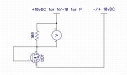
If you don't have a power supply, do you have a 9 volt battery and 100 ohm resistor? You could try this, watch polarity. Depending on the Vgs voltage (drain to source), current would be limited to 90ma through device.
Mad
PS don't leave power on too long.
If you don't have a power supply, do you have a 9 volt battery and 100 ohm resistor? You could try this, watch polarity. Depending on the Vgs voltage (drain to source), current would be limited to 90ma through device.
Mad
PS don't leave power on too long.
Attachments
Last edited:
Thanks Mooly.
Regarding test equipment, the only thing I have for testing transistors is a Micronata unit. I believe this pre-dates Mosfets, and so I don't know that it can be used to test them. Here's the manual, if anyone can advise on how to go about it.
I think you already have the information you need to test and match the MOSFETS (see post #50). This is a similar set-up as shown in the diagram in post #81, provided by MadInventor. Nelson Pass explains the matching process, and keeps it simple and practical.
My guess is the FET that was installed backwards is broken, as the drain voltage would be quite high (around 58 VDC), and this would probably break the FET, as the gate-source voltage should not exceed 14 volts. When the FET's in backwards, the source does not change (it's the case), but the drain and the gate pins are reversed. My other guess is that the other FET paired with the broken one is okay. But you should match the replacement to what is in there, or just get two new ones that match.
I think the internal diodes are there to protect from static electricity, and presumably high gate voltage, but given the specifications on the gate-source voltage limit, a voltage over 14, with significant current, would break them.
Thanks Mad and mmerig. I don't have a power supply (on my list), so the battery + resistor alternative is the way I'll go.
Makes sense about how the reversed FET could have died. Before I pulled it, I was wondering if it would even be possible to install it reversed because of the socket holes being in the wrong spots for the pins. But I saw that the pins were both bent at an angle from being forced in to the offset positions of the holes.
Makes sense about how the reversed FET could have died. Before I pulled it, I was wondering if it would even be possible to install it reversed because of the socket holes being in the wrong spots for the pins. But I saw that the pins were both bent at an angle from being forced in to the offset positions of the holes.
The Exicons are the current generation of lateral FET but Trollets offerings should be fine.
I've never used T03 sockets and so wouldn't know is available tbh. I'd be starting from scratch searching.
As to what has happened to this amp and the FET's, well that's open to speculation. These device are moderately static sensitive and so basic precautions should be used when handling them... no running on a nylon carpet and then grabbing hold of them, that kind of thing.
They do have inbuilt Zener diode protection on the gates and I wouldn't like to speculate on what incorrectly wiring one up would actually do.
Your amp plays, the bias control voltage adjusts OK and so I think you have to take the step of fitting new devices (just one pair at first though) and confirm all is good. A single pair is good for around 70 watts rms output and they really are tough when used correctly.
Have a look at the specs for this one... single pair of transistors. It was classic design and highly rated at the time (and still is).
How important is matching these FETs for this amplifier?
dbxdx5
That is sad, someone bent the gate and drain terminals over 3mm to get it in the socket. Like mmerig said, the back-to-back zeners are dust, they saw the full rail voltage. The gate is also toast. Call me curious, if you can measure the resistance from gate to drain and source, see how it failed.
Mad
Re. Matching of output FETs: In the construction article in 1983 Audio Amateur magazine Mr Borbely explained that he used source resistors to reduce marching requirement and that, in his experience, transistors in same batch would be ok without matching. In any case measurement of voltage across the resistors will expose any issue.
Good luck.
Glenn
Good luck.
Glenn
So from the latest posts it does indeed look like the FET's are going to be zapped. Matching isn't all that important because as Glen mentions, the amp has source resistors to help even things out. Even going further than that, the unique characteristics of laterals (unlike other transistor types they have a negative temperature coefficient) means that as one FET draws more current in a multiple pair, it heats up more and that action alone is enough to cause that FET to reduce its conduction. So they automatically balance out.
Testing FETs, and we probably all have our methods for this")
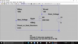
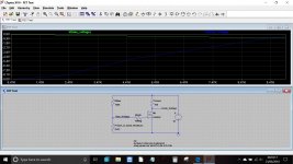
I would test the FET's like this, the reason being that we can see how the FET behaves under different gate voltages.
The gate of the FET should draw essentially zero current and so that is what the 10meg resistor is for. If the gate is leaky or damaged then the 10meg will show a problem. Forcing a gate voltage onto the FET might not show a problem in the same way.
The lower left resistor can be either a preset or a selection of fixed resistors. The voltage generated at the point marked 'Bias_Voltage' is simply ohms law. It is the 100k in series with your chosen resistor across 9 volts.
What should happen is that we can see how the FET behaves. With no gate voltage present (or more correctly no gate to source differential) the FET is OFF and no current flows. The drain voltage should therefore equal the battery voltage.
As the gate voltage increases (we plug in different value resistors) the FET should begin to turn on.
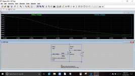
The graph shows resistor values from 470 ohm to 10k and the corresponding bias voltage they create. The drain voltage is also shown and you can read off the drain voltage vs gate voltage. Absolute values aren't critical, it is the fact that we see that at no bias voltage the FET is OFF and that as we approach 1 volt or so that the FET is fully ON.
The 'P Channel' FET simply has the supply reversed, the circuit now becoming a positive earth.
Testing FETs, and we probably all have our methods for this
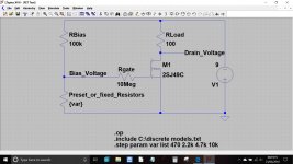
I would test the FET's like this, the reason being that we can see how the FET behaves under different gate voltages.
The gate of the FET should draw essentially zero current and so that is what the 10meg resistor is for. If the gate is leaky or damaged then the 10meg will show a problem. Forcing a gate voltage onto the FET might not show a problem in the same way.
The lower left resistor can be either a preset or a selection of fixed resistors. The voltage generated at the point marked 'Bias_Voltage' is simply ohms law. It is the 100k in series with your chosen resistor across 9 volts.
What should happen is that we can see how the FET behaves. With no gate voltage present (or more correctly no gate to source differential) the FET is OFF and no current flows. The drain voltage should therefore equal the battery voltage.
As the gate voltage increases (we plug in different value resistors) the FET should begin to turn on.
The graph shows resistor values from 470 ohm to 10k and the corresponding bias voltage they create. The drain voltage is also shown and you can read off the drain voltage vs gate voltage. Absolute values aren't critical, it is the fact that we see that at no bias voltage the FET is OFF and that as we approach 1 volt or so that the FET is fully ON.
The 'P Channel' FET simply has the supply reversed, the circuit now becoming a positive earth.
Attachments
I just picked up a used HP 6235A power supply on the cheap. So taking the battery out of the equation, I don't need the resistors to regulate the voltage. Perhaps a dumb question, but do I still want the 10 meg between the voltage and the gate?
And wiring this up, I'll have the common from the power supply running to the FET source (case), the +6V going to the gate, and my meter on the drain. Would my meter common go to the ground terminal on the back of the power supply?
And wiring this up, I'll have the common from the power supply running to the FET source (case), the +6V going to the gate, and my meter on the drain. Would my meter common go to the ground terminal on the back of the power supply?
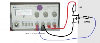
That looks an intriguing little power supply. Based on what I see...
The 'com' terminal is your zero volts or 'ground'. Your meter negative lead connects to this point.
The +18v terminal looks like it is adjustable between 0 and +18 volts. Check that it is.
Assuming the above is correct then just set the '+18' output to some convenient value... we suggested 9 volts.
The gate needs to be connected to a variable voltage in order to properly test the FET. That's what all the resistors do. Yes, you need the 10 meg (or something high, even 1meg would do) and you need the other two resistors to set the gate voltage.
So for the 2SK FET's the COM terminal goes to the Source.
The Drain has the series 100 ohm resistor which returns to the +18 terminal.
The gate has the high value resistor tagged to it, the other end of which needs a variable voltage to test the FET more comprehensively.
You can try a brute force test though. If you connect the 10meg to the Source (which is the COM terminal) then the voltage on the Drain should equal your supply voltage. That is because no current at all should be flowing in the 100 ohm.
If you now connect the 10 meg to the +6 volt terminal (check that there really is 6 volts present) then the Drain voltage should fall to a very low value, almost zero.
The above will only work for the 2SK devices, the 2SJ ones need a negative voltage (the -18 terminal) but would also need a negative 6 volt... but we can arrange that easily if needed.
Just check the 2SK's for now.
Just to add to the above... if the 6 volt output is adjustable as well then you have all you need to fully test the 2SK's. Varying the 6 volt output between 0 and just a volt or so should turn the FET fully on. Always keep the 10 meg in place though, never connect any voltage source directly to the gate.
Connect it like this, which does assume that the 6 volt output is variable and that it really does go right down to zero volts.
Your meter goes across the FET. Turn the gate voltage up and the voltage across the FET should fall. By the time you have just half a volt or so applied to the gate, the FET voltage should be nearing zero.
Your meter goes across the FET. Turn the gate voltage up and the voltage across the FET should fall. By the time you have just half a volt or so applied to the gate, the FET voltage should be nearing zero.
Attachments
Hi
the resistor is always a good idea from any voltage source to limit the current. Do not remove the resistor. Mosfets are sensitive to ESD. Take care to remove any possibility of Electrostatic discharge - particularly gate
Yes, it so easy to cause damage, and not just from ESD. Connecting the gate directly to a low impedance voltage source would be asking for trouble as the internal protection zeners have very limited current handling capacity.
Ok, so the power supply does go from 0 to 6V and 0 to +/-18V.
To recap, I'm using the 6V output for the 2SK's and the +18V for the 2SJ's.
I don't have a 10 meg resistor handy, only a 1 meg and a 20 meg, so I'll go with one of those. One end goes to the Gate, the other to the voltage output from the power supply.
My DMM COM black lead goes to the COM connection on the power supply, not the ground connection on the back of the chassis. The COM comnection from the power supply is connected to the Source. Right?
The 100 ohm goes between the Drain and the +18V output on the power supply, though I'm not sure why.
The red voltage probe from my DMM is going to the Drain. I think. . . .
The 100 ohm is just a load resistor to limit current flow. With the FET off you have the same voltage at each end of the resistor. As the FET conducts it pulls the voltage on the Drain lower.
Think of the FET in the OFF state as having infinite resistance. So you have 100 in series with infinity across 9 volts. What is the voltage across our 'infinity' ? Its 9 volts.
Now bias the FET so it conducts a little. Lets say the FET now appears as a 100 ohm resistor (like the load). What is the voltage across the FET now ? Its 4.5 volts.
With the FET fully on it will approximate to a 1.5 ohm resistor. The voltage across the FET now would be around 60 millivolts.
(providing there is no stray pickup such as radiated RF etc then 20meg, 200 meg or 2000 meg would all work the same because the gate is voltage driven (unlike a regular transistor) and draws virtually no current. However at those high impedances even putting a finger near the gate could be enough to induce voltage and upset readings. So 1 meg is fine).
Think of the FET in the OFF state as having infinite resistance. So you have 100 in series with infinity across 9 volts. What is the voltage across our 'infinity' ? Its 9 volts.
Now bias the FET so it conducts a little. Lets say the FET now appears as a 100 ohm resistor (like the load). What is the voltage across the FET now ? Its 4.5 volts.
With the FET fully on it will approximate to a 1.5 ohm resistor. The voltage across the FET now would be around 60 millivolts.
(providing there is no stray pickup such as radiated RF etc then 20meg, 200 meg or 2000 meg would all work the same because the gate is voltage driven (unlike a regular transistor) and draws virtually no current. However at those high impedances even putting a finger near the gate could be enough to induce voltage and upset readings. So 1 meg is fine
).Ok, so the power supply does go from 0 to 6V and 0 to +/-18V.
To recap, I'm using the 6V output for the 2SK's and the +18V for the 2SJ's.
The red voltage probe from my DMM is going to the Drain. I think. . . .
Look at the earlier posts (Post 88) showing the correct voltages at different PINs of P and N type Mosfets (only the Polarity changes for 18V) What Mooly's diagram is for 2SK (N FET) with +18V ( post 93)

The light bulb finally clicked on. Thanks Mooly and kannan_s. I'll test the 2SK FET's and let you know what I found.
Also - keep the voltage to 9V (+_ depending on the Mosfet) on the HP 6235 Power supply before connecting!
- Status
- This old topic is closed. If you want to reopen this topic, contact a moderator using the "Report Post" button.
- Home
- Amplifiers
- Solid State
- Borbely DC 100 Amp: Left Channel Troubleshooting