I think that this not only semantic issue was well described by Walter Kester (AD)
Feedback from the
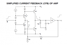
output to the inverting input acts to force the inverting input current to zero, hence the term Current Feedback. (In the ideal case, for zero inverting input impedance, no small signal voltage can exist at this node, only small signal current).
Consider a positive step voltage applied to the non-inverting input of the CFB op amp. Q1 immediately sources a proportional current into the external feedback resistors creating an error current which is mirrored to the high impedance node by Q3. The voltage developed at the high impedance node is equal to this current multiplied by the equivalent impedance. This is where the term transimpedance op amp originated, since the transfer function is an impedance, rather than a unitless voltage ratio as in a traditional VFB op amp.
Attachments
Hi All,
I'm not sure if somebody mentioned this already, but if you try to look at any node in the circuit from the impedance ratio point of view - everything becomes pretty clear.
If you drive a high-impedance node from the low-impedance output - you drive with voltage. Example - driving the base of the next stage from emitter of the previous one. Voltage drive.
If you drive a low-impedance node from the high-impedance output - you drive with current. Example - driving the emitter of the next stage from collector of the previous one. Current drive.
This is true for any kind of node - active or passive one. The driving/driven impedance ratio shows what you drive the node with.
Pavel - good explanation, in line with what I just mentioned.
Cheers,
Valery
I think Bob Cordell wrote something like that.
In a CFA circuit, the inverting input presents a low impedance (let's says 10 Ohm, typical) and the feedback divider midpoint presents a high impedance (100 or a bit more, typically). So, according to the impedance ratio point of view, the inverting input should be defined as current driven.
There is nevertheless a very curious fact which prevents to blindly adher to such a conception. I found the following gains in simulation of very basic CFAs with various values of feedback networks
input with a single transistor :
Ra 9 Ohm, Rb 1 Ohm -> gain -> 9.99
Ra 9k Ohm, Rb 1kOhm -> gain -> 9.92
input using a diamond circuit :
Ra 9 Ohm, Rb 1 Ohm, gain -> 9.92
Ra 90 Ohm, Rb 10 Ohm, gain -> 9.85
Ra 900 Ohm, Rb 100 Ohm, gain -> 9.26
Ra 9 kOhm, Rb 1 kOhm, gain -> 5.78
Hence the low impedance of the inverting input does not load the feedback divider as it could be expected by the impedance ratio point of view.
What does happen ?
The low impedance inverting input is also a low impedance voltage output, value of which is almost the voltage present at the non-inverting input.
When closed, the feedback forces the amp output to be such that the voltage at the feedback divider midpoint to follow the non-inverting input voltage.
In the first analysis, the impedances of the inputs do not play a major role in the voltage gain of a CFA.
Last edited:
A little off topic (sorry) but now this thread has been settled (one hopes!), I just started a new thread at Music, Feedback and Everything for an article google turned up encapsulating many of the concepts of feedback with some distinct audio references (?). It does not appear so off-topic as you might first think! And it does make you think! Has anyone else read it or know more about it?
What shall we call an amplifier that actually has current feedback then?
In the german book
Halbleiter-Schaltungstechnik: Amazon.de: Ulrich Tietze, Christoph Schenk, E. Gamm: Bucher
there are mentioned four different amplifier stage versions - chapter 5.3 for basics arround operational amplifiers under
https://sisis.rz.htw-berlin.de/inh2009/12374633.pdf
1) CC
2) VV
3) VC
4) CV
the first term stands for the NFB input behaviour and the second term for the output behaviour.
"C" means low impedance (current controlled) at the NFB input and "V" means high impedance (voltage controlled).
At the output the conditions are reversed.
Thus I call such an amplifier "CC-Amp", even in case of a completly discrete A power amp according the AD844 circuit or with an AD844 as front-end.
check also out page 3 under
http://alt.ife.tugraz.at/LV/AST/OV2.pdf
Unfortunately I don't find these descriptions in the english language.
Most usual power- and pre-amps are at both inputs high impedance character, thus I call these amps still VC amps, except for cases of an realized inverted mode.
Last edited:
That's a riddle, surely.What shall we call an amplifier that actually has current feedback then?
Here's another. Look up this thread: Has anyone seen Rush pairs used this way? For a CFA with true differential inputs
The riddle is this: Post 3 (link above) shows an input stage that has one high input resistance and one with a medium input resistance. Does this make it a CFA input stage?
The 'medium' input resistance input has Beta times the input resistance of the standard CFA inverting input so very little current flows into the inverting input via the feedback resistor. With very little current flowing through the feedback resistor can we still call it a "current feedback" amp?
More usual terms :In the german book
Halbleiter-Schaltungstechnik: Amazon.de: Ulrich Tietze, Christoph Schenk, E. Gamm: Bucher
there are mentioned four different amplifier stage versions - chapter 5.3 for basics arround operational amplifiers under
https://sisis.rz.htw-berlin.de/inh2009/12374633.pdf
1) CC
2) VV
3) VC
4) CV
the first term stands for the NFB input behaviour and the second term for the output behaviour.
"C" means low impedance (current controlled) at the NFB input and "V" means high impedance (voltage controlled).
CCCS Current Controlled Current Source
CCVS Current Controlled Voltage Source
VCCS Voltage Controlled Current Source
VCVS Voltage Controlled Voltage Source
I would like to propose a way of answering Nelson Pass’ question unambiguously.
All amplifiers have input stages that carry current. We can ask after the source of this current.
The inputs of “standard” op amps like the hoary ‘741, ‘709 and TL082 accept minimal to negligible currents in comparison to the those carried through the collectors/emitters and drains/sources of their input stages. These larger currents come from a DC current source which is steered by voltages applied to the inputs. Practically no part of these currents comes from feedback from the output. For these reasons, these are VFAs.
Then there are amplifiers whose input stage emitters, cathodes or sources are connected to their inverting inputs. ( What the industry has taken to calling CFAs are in this class.) These may be biased from DC current sources or through passive component networks which are connected to the amplifier output and possibly to an excitation source for the amplifier. Let’s convert these to a Thevenin equivalent. We have a voltage source which is a weighted sum of the output and excitation signals connected to the input through a single impedance element. Current flows from this source (which contains the output signal) into the input stage where it constitutes the input stage signal current. Significant current is being fed back from the output into the input. This is a justification for calling these CFAs.
While it is true that certain performance characteristics depend on whether the impedance of the Thevenin equivalent or that of the inverting input is the larger, this is a possible unambiguous means of distinguishing between VFAs and CFAs.
Leads to definitions of amplifiers
This leads to a conclusion whereupon the nature of a node, being a current or voltage node, is dependent upon the impedance of the node and the source impedance of the network feeding the node. This makes sense.
It can be defined that whenever the source impedance of the device feeding the node is greater than the impedance of the node itself, the node can be classified as a current node. If not it can be classified as voltage node. It follows that in the vast majority of so called "CFA" implementations the feedback source has an impedance (feedback resistors + ) much greater than the typical 30 to 50 ohm input resistances. Hence to configure a "CFA" as a "VFA" requires that the feedback network be less than 50 ohms to characterize these amplifiers anything other than a CFA.
Implementations of so called "CFA" amplifiers are dominated by implementations as CFA's. It doesn't seem logical or helpful to identify them any other way. It is only on the rarest of occasion by designers that understand their nature that would use them in any other way.
There is no argument that a common base circuit produces output currents as a function of variant Vbe voltages. However in current feedback amplifiers the Vbe varies in accordance with the local feedback of current flowing through the feedback resistance. In other words the emitter adjusts itself according to current passing through a resistor no differently than a voltage follower. In other words it is feedback current that causes Vbe to adjust.
Hi All,
I'm not sure if somebody mentioned this already, but if you try to look at any node in the circuit from the impedance ratio point of view - everything becomes pretty clear.
If you drive a high-impedance node from the low-impedance output - you drive with voltage. Example - driving the base of the next stage from emitter of the previous one. Voltage drive.
If you drive a low-impedance node from the high-impedance output - you drive with current. Example - driving the emitter of the next stage from collector of the previous one. Current drive.
This is true for any kind of node - active or passive one. The driving/driven impedance ratio shows what you drive the node with.
Pavel - good explanation, in line with what I just mentioned.
Cheers,
Valery
This leads to a conclusion whereupon the nature of a node, being a current or voltage node, is dependent upon the impedance of the node and the source impedance of the network feeding the node. This makes sense.
It can be defined that whenever the source impedance of the device feeding the node is greater than the impedance of the node itself, the node can be classified as a current node. If not it can be classified as voltage node. It follows that in the vast majority of so called "CFA" implementations the feedback source has an impedance (feedback resistors + ) much greater than the typical 30 to 50 ohm input resistances. Hence to configure a "CFA" as a "VFA" requires that the feedback network be less than 50 ohms to characterize these amplifiers anything other than a CFA.
Implementations of so called "CFA" amplifiers are dominated by implementations as CFA's. It doesn't seem logical or helpful to identify them any other way. It is only on the rarest of occasion by designers that understand their nature that would use them in any other way.
There is no argument that a common base circuit produces output currents as a function of variant Vbe voltages. However in current feedback amplifiers the Vbe varies in accordance with the local feedback of current flowing through the feedback resistance. In other words the emitter adjusts itself according to current passing through a resistor no differently than a voltage follower. In other words it is feedback current that causes Vbe to adjust.
Operational amplifiers can be identified as a VFA or a CFA from the perspective of dependent and independent variables in accordance with Ohms Law. For the discussion we can examine a VFA and CFA having an inverting input impedance of 10Mohm and 50 Ohm respectively.
When V1 is output from a theoretical zero output impedance voltage source and applied to the inverting terminals of a VFA and CFA the resulting current becomes 1/10MOhm for the VFA and V1/50 Ohms for the CFA. In both cases V1 is an independent variable that causes current to flow in accordance with ohms law. Because the current is a dependent variable in both cases, both are pure VFA’s.
In contrast, when I1 is output from a theoretical voltage source of infinite output impedance (hence infinite voltage) as thereupon a pure current source, and this applied to the inverting terminals, the output voltage becomes I1x10MOhm for the VFA and I1x50 for the CFA. In both cases I1 is the independent variable causing voltage to appear across the inverting input resistors. Because voltage is a dependent variable both can be classified as pure CFA’s.
This is to suggest that for any real world voltage source driving the inputs having non-zero or non-infinite source impedance there is no such thing as a pure CFA or VFA and that both a VFA and CFA must convert from being one to the other at some point. As the only term that is available to us is the value of the input impedance it appears logical to identify the crossover point as equal to the inverting input impedance of the CFA or VFA devices.
What this means is that a VFA can be only be characterized as a VFA when the source to which it is attached has an impedance less than 10MOhm in the VFA example above, and that a CFA can only be characterized as a CFA when the source to which it is attached has an impedance greater than 50 ohms in the CFA example.
Using such criteria it is interesting to examine a feedback network shown in the application note of the AD844. The AD844 has a 50 Ohm Ri on the inverting terminal. Figure 32 on page 14 of 20 shows a non-inverting feedback amplifier having a feedback resistor from the output to the inverting terminal of 499 Ohms and a resistor from the inverting terminal to ground of 4.99 Ohms (gain of about 100). This means that the source impedance feeding the inverting terminal is the parallel combination of these two resistors, or about 5 Ohms.
If one uses the criteria above, the amplifier in Figure 32 is dominantly configured as a VFA, not a CFA. In other words the feedback divided voltage has a source impedance of 5 Ohms, far lower than the input 50 Ohms of Vin, hence the input can be considered driven by voltage. From the above a CFA must become a VFA if the source impedance becomes 0 Ohms. This begs the question, "If the configuration in Figure 32 is not yet a VFA then when does it become one?"
_______________________________________________
"Logic is the systematic method of coming to the wrong conclusion with confidence"
I find much to agree with about what you've written, Hierfi. It is the ratio of the impedance seen by the feedback input to that OF the feedback input which determines important characteristics such as whether or not the bandwidth is inversely proportional to closed loop gain. As such, no amplifier is inherently CFA or VFA, but the combination of a feedback network and an amplifier is.
Even so, I find it useful to acknowledge the following: the signal current flowing in what we call a standard VFA input stage does NOT come from the VFA output. On the other hand, a significant portion of that current in what we call a CFA input stage does come from the CFA output (all of it, actually, in a non-inverting mode.) This becomes clear if the output and network are replaced with a simple Thevenin equivalent.
In that sense, we could justify classifying amplifiers alone as either CFAs or VFAs: the signal current in CFA input stages is fed back from the output; that in a VFA input stage is not, but rather is controlled by the voltages fedback from its output and applied to excite the circuit.
I find it useful to acknowledge the following: the signal current flowing in what we call a standard VFA input stage does NOT come from the VFA output. On the other hand, a significant portion of that current in what we call a CFA input stage does come from the CFA output (all of it, actually, in a non-inverting mode.) This becomes clear if the output and network are replaced with a simple Thevenin equivalent.
Hi CPaul. There seems little difference between the networks feeding the so-called trans-impedance node in a CFA to that of the impedance node in a VFA. Both can be considered requiring similar currents in generating the voltage feeding the output buffer. Hence the differences required to drive these nodes is variant by the current gain in the VFA connection, as being reduced at the input by this gain. This implies that the only difference between a CFA and VFA is that the VFA has current gain in driving the voltage generating node and the CFA doesn't. This doesn't seem as a convincing argument to discriminate one as being current driven and the other not.
Data sheets are normally created by manufactures to assist designers in implementing their devices. From a designers perspective, the term "CFA" can be considered as a simplistic mnemonic characterization of "a network configured of electronic parts in a specific way". This mnemonic is useful to decide between looking at lists of so-called VFA's or CFA's. How these devices are used, with feedback or otherwise, the manner of connection to variant nodes, the adherence to a manufacturers data sheet, and if the words associated with the mnemonic properly reflect the network can be "don't cases" to designers.
It is nevertheless interesting to rationalize what is meant by calling these complex arrangements as being a "voltage feedback amplifier" or "current feedback amplifier" . The inclusion of the letter "F" in "CFA" and in "VFA" seems irrelevant of inclusion to contribute in the descriptor of such devices. Both VFA's and CFA's are capable of operating to DC. This means that at some fixed DC input voltage these amplifiers produce some output voltage in accordance with a resistive network connected back to the inverting terminal. If we disconnect the output voltage from the feedback network and replace this with a DC source of equal voltage, as feeding the same resistive network, the output voltage and the DC source voltages would continue to match.
This suggests that feedback is not a relevant condition in the determination of its operation in what can then be more simply described as a voltage amplifier "VA" or current amplifier "CA". The above leads to a conclusion supporting a nodal examination as the only mechanism in the determination of the behaviour of inputs as responding to voltage or current. This seems where this thread is ultimately heading.
Hi All,
I'm not sure if somebody mentioned this already, but if you try to look at any node in the circuit from the impedance ratio point of view - everything becomes pretty clear.
If you drive a high-impedance node from the low-impedance output - you drive with voltage. Example - driving the base of the next stage from emitter of the previous one. Voltage drive.
If you drive a low-impedance node from the high-impedance output - you drive with current. Example - driving the emitter of the next stage from collector of the previous one. Current drive.
This is true for any kind of node - active or passive one. The driving/driven impedance ratio shows what you drive the node with.
Cheers,
Gerrit
_____________________________
And in the immortal words of Gilda Radner on SNL "Oh!... never mind"
I'm not sure if you think I was saying something like, "the VFA has current gain in driving the voltage generating node and the CFA doesn't." That was not my intent.
Your point about the irrelevancy of the "F" in the amplifier names is taken; it is unnecessary. However, I disagree that that leads to the conclusion of "nodal examination as the only mechanism..." for the following reason.
Whether employed in open or closed loop configurations, negligible portions of a VFA's input stage signal current come from its output or from a signal source external to the amplifier. But such current in a CFA comes only from such sources. This is a noteworthy distinction at least because it translates into an innate feature of the CFA which an unenhanced VFA lacks: slewing current on demand. Impedance ratios won’t reveal the presence or absence of such.
Still, I agree that the impedance ratio is important - it informs regarding the question of constant bandwidth vs. constant gain-bandwidth. But it is not the sole key to distinguishing between basic CFAs and VFAs.
Finally, I'm afraid I don't understand the clause containing the phrase "don't use". But anyone who remembers Miss Emily Litella is OK in my book!
CFA reprise
Indeed, Walt Kester did a great job, and this work is all available for DIYAudio readers here.
A summary of the CFA discussion on my (now missing) Waltsblog is here. Resurrected now, for better or worse. Links within should still work.
Walt Jung
I think that this not only semantic issue was well described by Walter Kester (AD)
Indeed, Walt Kester did a great job, and this work is all available for DIYAudio readers here.
A summary of the CFA discussion on my (now missing) Waltsblog is here. Resurrected now, for better or worse. Links within should still work.
Walt Jung
It is not a matter of impedance ratio, but difference in signal strength. Gate / base serving as the input terminal implies a voltage signal, while source / emitter serving as the input terminal implies a current signal.
Sorry but it's nothing to do with the signal strength (whatever you mean by the signal strength).
I found Chris Paul's recent article in AX very well balanced and insightfull.
Since that I also discovered (actually it was Ian Hegglun who made me aware) the attached presentation by TI's Xavier Ramus.
As with many (all?) things engineering, some designs shine is a specific design concept, while other shine in another context. It's another 'it depends'.
Jan
Since that I also discovered (actually it was Ian Hegglun who made me aware) the attached presentation by TI's Xavier Ramus.
As with many (all?) things engineering, some designs shine is a specific design concept, while other shine in another context. It's another 'it depends'.
Jan
No more thoughts?
Well here's another great resource, Chris's articles, kindly posted by AX's editor:
Current Feedback: Fake News or the Real Deal? | audioXpress
Jan
Well here's another great resource, Chris's articles, kindly posted by AX's editor:
Current Feedback: Fake News or the Real Deal? | audioXpress
Jan
Plug it in, try it out. Measure it. Listen to it. Experiment.
If you're pleased with the results, wonderful. If you're not pleased, that's too bad, but at least you learned something and meanwhile you had fun doing "new frontier" work in your hobby.
If other people want to argue about the words used, let them. It doesn't change your measurements or your listening preferences.
- Home
- Amplifiers
- Solid State
- Current Feedback Amplifiers, not only a semantic problem?