Member
Joined 2009
Paid Member
I was always impressed by the design of the 'KRILL' amplifier, developed and sold commercially by Steven Dunlap. He presented his amplifier here: http://www.diyaudio.com/forums/solid-state/134619-krill-little-amp-might.html
I'd like to build one of these amplifiers, with some modifications. I've found relatively few comments on listening impressions for this amplifier, but those I did find were all positive. I'd like to use two output pairs like here: Krill construction thread - 100W version
I'd be interested to know if there are any recent updates from forum members that have built and/or heard this amplifier.
Edit: Note that the attached pdf schematic shows D20 and D22 incorrectly oriented.
Attachments
Last edited:
Gareth,
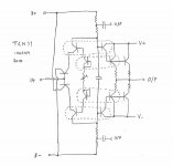
I have been interested in this amp since 2008, and if you build one and carefully examine the technical and sonic features I would be most grateful. I once described a description of why it worked, but many do not agree. You are the right man to get to the bottom of it.... it's a very elegant, but perplexing bias generator. I see this as pretty much the guts of it.
Cheers,
Hugh
You would be well advised to look for Edmond Stuart's opinion about it.... he is not someone to underestimateI was always impressed by the design of the 'KRILL' amplifier, ....
Member
Joined 2009
Paid Member
I have read a fair bit about the amplifier on the threads that I linked in the first post. There are both positive and negative opinions on the technical strengths and weaknesses of the Krill amplifier. However, I have found only a few people who have built it, most were simply enjoying the banter. Those people who built it and who posted listening impressions (not just on this forum, I also had private correspondence several years ago from an old friend of Hugh's) were all positive. Some of them were very positive.
And the basic Diamond Buffer output stage has been well regarded for a long time.
And the basic Diamond Buffer output stage has been well regarded for a long time.
The first time I saw that, I immediately realized that it couldn't deliver: it reminds me of elaborate "overunity" schemes (or scams) where the rational guy trying to analyze it is led into endless circles.
Initially, I rejected this first analysis because so many supposedly clever people cannot possibly be misled in this way, but seeing Edmond's reaction I knew that I was right.
Note that it seems to work, and can be made to, and I have also come up (independently, and before) with a scheme that looks superficially different, but uses some of the same underlying principles, although in a conscious and deterministic way, and there is a price to be paid... as always
Member
Joined 2009
Paid Member
Well, a lot of folk got excited about what the amplifier does and what it doesn't do. You know how this forum breeds debate. I'm not at all concerned about those arguments, in the end there is very little mystery about what it does and what it doesn't do - I credit 'Andyc' and Steven Dunlap for my understanding of it. However, I am interested to hear of any further listening impressions if anybody else actually built it ?
Member
Joined 2009
Paid Member
I'm going to make some changes to the original Krill design. What I have in mind is:
a) the voltage gain stage will be a feed-foward, simple transistor amplifier without feedback dc-coupled to the Krill output buffer. I will adjust the front-end power supply rails to operate at a higher voltage (e.g +/-70V)
b) the constant current sources will hang off the front-end power supply rails and to avoid having to heatsink these devices I'll replace them with a R + C + R bootstrapped current sources
c) the original had some variations on thermal control, or at least there was a fair bit of chit-chat. I'll be using two diode-wired-transistors for the bias string and each will be placed in direct contact with an output power transistor. The bias transistors will each be placed in direct contact with a driver transistor. Based on spice simulations this provides good control.
d) I will use a discrete transistor dc-servo.
All good ideas Bigun.
In your shoes, I'd do the same. CCS ruin the sound, single transistor VASs sound best, a single discrete servo avoids the complexity of a bipolar power supply, but I would think for a time about the thermal control. I like a cutback Vbe multiplier, but it's my preference.
HD
In your shoes, I'd do the same. CCS ruin the sound, single transistor VASs sound best, a single discrete servo avoids the complexity of a bipolar power supply, but I would think for a time about the thermal control. I like a cutback Vbe multiplier, but it's my preference.
HD
Member
Joined 2009
Paid Member
That's an interesting option but I wasn't happy using a Vbe multiplier with so little current available through the bias string in the Krill bias generator - it's paltry but apparently works OK with diodes. The diode-wired transistors are better than a lot of regular diodes and physically easier to mount. But having no feedback anywhere you soon realize all the benefits of feedback on things like PSRR, stable gain, automatic control of the VAS current, automatic dc-servo control etc.
It looks like a lot of work to prototype something up on the bench so I'll do a pcb and be prepared to re-spin the design once I've discovered it's foibles.
It looks like a lot of work to prototype something up on the bench so I'll do a pcb and be prepared to re-spin the design once I've discovered it's foibles.
Member
Joined 2009
Paid Member
Member
Joined 2009
Paid Member

Member
Joined 2009
Paid Member
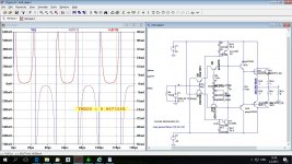
Here is what I simulated four years ago, but never built it.
Hi Dadod,
I get the same results, more or less, from my simulations. There was a lot of discussion on this topic in the various Krill threads. Some people really took Steve to task on his claim of non-switching and it became a bit tense but this forum can be a good place to pull things apart and carefully examine them.
The non-switching character of the Krill design is due to the slow turn-off of the power output transistors whilst the minority charge carriers are swept out of the base region. This is something that is normally considered to be a bad parasitic property of BJT's. Because it is a transit-time effect there is a strong frequency dependency - the transistors don't have time to turn-off completely at high frequencies but they do turn off at low frequencies. This parasitic behaviour is usually 'solved' with a capacitor between bases of the complementary output devices. In Krill this capacitor is not used. The quasi-comp and CFP type of output structures also suffer from this parasitic cross-conduction. It can lead to over-heating of the output stage if driven hard at high frequencies (NAIM restricted the bandwidth of their early pre-amps to mitigate this risk with their original quasi output amplifiers).
The Krill bias scheme is a Red Herring in this regard. There was a lot of discussion about it and some great ideas of how it might be working. But in my mind it is a simple story - the bias transistors are operated at very low Vce and are essentially saturated. They behave like resistors and there is no meaningful variation in their base current with signal. There is no special dynamic behaviour going on there that affects the amplifiers switching or non-switching. But it is an elegant method of biassing the amplifier and I'm retaining it in my project. It doesn't help that spice simulations sometimes fall-down on proper coverage of saturation behaviour in certain device models and parasitics which are important in this design - there were various reports of simulated results not matching measured results.
Whether this parasitic non-switching behaviour is important for the sound I can't say. It is clearly NOT the kind of non-switching you get in a Class A amplifier and I am doubtful about it being critical for the sound here. I believe the most critical feature of this amplifier is the lack of global feedback. I have extended this thought to modify the voltage gain stage. Instead of the Krill voltage gain design which uses a feedback topology I am using an open-loop common emitter amplifier. The design is based on feed-forward error correction. The design was published by Mr. Kulish in Russia. It's a derivative of the Sandman iterative error take-off approach (Class S anyone ?). It requires a good deal of voltage headroom, has a high output impedance and poor PSRR. It's not unlike a vacuum tube voltage gain stage.
Last edited:
Hi bigun,
Maybe you can use the IPS (current conveyor) from the amps in this thread. It has quite low distortion and high gain. http://www.diyaudio.com/forums/solid-state/260308-gainwire-ngnfb-classb-poweramp.html#post4018576
There was discussion about Kulish circuit a time ago in this forum and I simulated it and came to conclusion that is not easy to get enough gain with it.
Damir
Member
Joined 2009
Paid Member
The Kulish can provide plenty of gain if you choose a high enough ratio of resistor values in collector load vs emitter load. This is simply the situation with a classical common emitter amplifier.
The challenge with the Kulish is that it uses a simple resistor collector load. In contrast, most feedback amplifiers use a constant current source, either a transistor based design or a R+C+R bootstrap. The Krill amplifier takes that approach. The constant current source provides a very high collector load impedance to provide for very high gain without needing a lot of headroom. In fact you want very high gain in a feedback amplifier because you are going to use it for decent feedback factors.
For this project we have no feedback. And so it is more like a tube amplifier. For the simple single resistor collector load required by the Kulish approach you have to think like a tube amplifier designer. This means you want to have a large voltage headroom. If this were a pentode gain stage I would want at least 140V of B+ supply available.
Well, this is what I have indeed decided on. The dual rails of the Krill amplifier power supply are voltage doublers with zener-emitter-follower regulators. They can be configured to allow for a +/-70V supply to the front-end of the amplifier. This allows the Kulish to be operated with decent headroom. It may not be enough for low distortion at 100W but I'm not building for 100W. I'm using the 100W Krill baseline design only in so far that it provides two pairs of output devices - this is desirable for lower distortion in the output stage.
Last edited:
Bigun:
This book contains some interesting ideas. I think it's worth taking a look considering what you're describing.
https://linearaudio.net/books/2220
mlloyd1
P.S. Damir, you too!
🙂
This book contains some interesting ideas. I think it's worth taking a look considering what you're describing.
https://linearaudio.net/books/2220
mlloyd1
P.S. Damir, you too!
🙂
Member
Joined 2009
Paid Member
well I never expected a whole book on the topic !
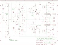
Here's the design approach I favour (attached).
Here's the design approach I favour (attached).
Attachments
Last edited:
could not resist...
Hi Bigun!
I am so excited to see you are working on Krill,
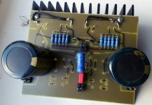
~10 years ago I mounted it as p2p and it worked excellent (OPS only),
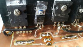
then I started to mount it on "pcb" (grooved Cu laminate as show the pictures),
... and it was sleeping in the box until now...
My plan is not sophisticated like your, I will not build the protection,
and for the preamp I am going to use cfp hybrid ECC88+MJE15033 powered from boosted + rail (+40 to +80VDC) like in original Steve's design.
Hi Bigun!
I am so excited to see you are working on Krill,
~10 years ago I mounted it as p2p and it worked excellent (OPS only),
then I started to mount it on "pcb" (grooved Cu laminate as show the pictures),
... and it was sleeping in the box until now...
My plan is not sophisticated like your, I will not build the protection,
and for the preamp I am going to use cfp hybrid ECC88+MJE15033 powered from boosted + rail (+40 to +80VDC) like in original Steve's design.
Attachments

Member
Joined 2009
Paid Member
- Home
- Amplifiers
- Solid State
- TGM11 - no GNFB - inspired by Steven Dunlap 'KRILL'