I didn't try grounding with resistors... I have tried DC heating in the other design with low PSRR, but even there it did not give any advantage. So I have "relaxed", leaving just floating AC ")
With regards to 12AX7 - we just recently had a discussion with Ray Waters in the other thread - he pointed out the positive bias (grid is more positive than cathode) in this kind of design, resulting in some grid current increase, which is not so good. My simulation confirmed positive bias, so I didn't even try it in the live prototype
Looks looks in such conditions 12AU7 is virtually unbeatable
thimios
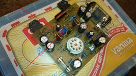
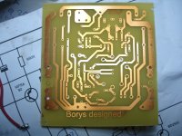
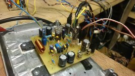
The 4 diodes 1N4148 are clamping the bias spreader 1k potentiometer just in case the failure, 3 diodes prapobly will do the job too. On the picture (post#22) there is the basic/simplest version of the amp (I am going to improve it a bit, later on).
The next step is HD version (currently tested). There was room for the potentiometer at the cathodes just in case I was going to use DC coupled instead a capacitor in NFB.
The finished HD version full documentation is bellow (12UA7).
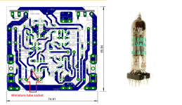
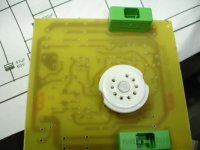
At post #14 there is picture of HD version running with mini tube, there is additional LTP inbetween input and VAS stage so the working point of triode can be setted without any further modyfication.
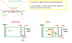
Now I am testing the miniature tube's, I found a small improvement just by symetrising the heater winding with 2 x 100R resistors.
The 4 diodes 1N4148 are clamping the bias spreader 1k potentiometer just in case the failure, 3 diodes prapobly will do the job too. On the picture (post#22) there is the basic/simplest version of the amp (I am going to improve it a bit, later on).
The next step is HD version (currently tested). There was room for the potentiometer at the cathodes just in case I was going to use DC coupled instead a capacitor in NFB.
The finished HD version full documentation is bellow (12UA7).
At post #14 there is picture of HD version running with mini tube, there is additional LTP inbetween input and VAS stage so the working point of triode can be setted without any further modyfication.
Now I am testing the miniature tube's, I found a small improvement just by symetrising the heater winding with 2 x 100R resistors.
Attachments
Last edited:
WOW
thimios
You suprised me a lot.
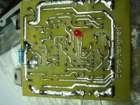
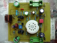
Yes this board is usable, it is the one from first post. I have started my tube journey with it.
If you have good DC 12.6V source (+-10%) for heater that is ok. If you do not have it you can make a very small modyfication for 6,3V ac heater connection (I will make a drawing).
I am going to fine tune this board a bit.
Bellow You have a screan for the elements, top layer and eagle files so You can print it.
thx
Peter
thimios
You suprised me a lot.
Yes this board is usable, it is the one from first post. I have started my tube journey with it.
If you have good DC 12.6V source (+-10%) for heater that is ok. If you do not have it you can make a very small modyfication for 6,3V ac heater connection (I will make a drawing).
I am going to fine tune this board a bit.
Bellow You have a screan for the elements, top layer and eagle files so You can print it.
thx
Peter
Attachments
Last edited:
Now imprtant thing is how does the amp turn on.
- power ON rails + heater supply
- after around 7s current is starting to flow threw cathodes
- just after that NFB is starting to work and is correcting the DC offset
- after 10s amp is ready to eat the speakers
I am using integrated PSU with DC protect so all is automated.
thimios
The potentiometer just by the tube socket (100R) dont solder it (leave it ac coupled).
Thanks again ,for first test i will use regulated d.c for filaments.Now imprtant thing is how does the amp turn on.
- power ON rails + heater supply
- after around 7s current is starting to flow threw cathodes
- just after that NFB is starting to work and is correcting the DC offset
- after 10s amp is ready to eat the speakers
I am using integrated PSU with DC protect so all is automated.
thimios
The potentiometer just by the tube socket (100R) dont solder it (leave it ac coupled).
Hi Guys
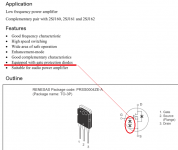
I would rather not replace a $10-15 mosfet for the sake of saving on some 21-cent zeners. In my experience the internal zeners used in many mosfets are not as robust as ones you would add to the circuit. Gate-stops are expected to be in place, but it seems like much larger than usual ones are expected by the device manufacturer - could just be the old devices from the '80s?
Anyway, to each his own.
have fun
Now i have a dilemma to finalize the simple version or not?Junm
I have small pcb for mini tubes, the amp is playing now, today evening I will post the pcb board.
thx
Peter
That will be nice and I will wait for it....thanksJunm
I have small pcb for mini tubes, the amp is playing now, today evening I will post the pcb board.
thx
Peter
I just looked at this thread.
Very nice design! I did not know you could run these tubes at such a low anode voltage.
What are they like noise-wise?
Hi Andrew,
Yes, 12AU7 is a cool creature - my prototypes show the same experience. As soon as it's got +33-35V at its anodes (assuming cathodes are at around +1V), it feels good. At 25V it still runs, but 2-nd harmonic increases about 10 times...
And it's rather low-noise and high-linearity one at the same time

Cheers,
Valery
Last edited:
I got the small board for mini tubes up and running.
The cathode is at +0.7V (hope that is enough).
Valery
You are right there is quite a loot of 2nd harmonic with low anode voltages but it does not disturb while listening.
I got some small problems with the v5 mini tube pcb (I am not sure why).
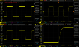
Instead MPSA i have used 2N5xx1 transistors and I had 2.6MHz 3V sine at the output,
to get rid of it I had to add second miller capacitor in VAS (so there are two miller caps now). The compensation cap at the NFB resistor --> 18pF-22pF. Now all is good.
I have added the gate zeners as Struth advised to do.
Bonsai
I am checking the hum/noise with 2R speaker, noise can be heared when I put my ear into the speaker, from 10-20cm noise can not be heard.
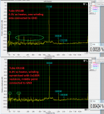
The 12AU7 is way better heare than 6N16B, take a look post 23 --> the hum is quite low.
thimios
If you have the board and few components soldered it is really 15-25min to get it up and running, this is very basic and simple amp.
Bellow some usfull files for version HD with mini tubes. (schematic, pcb and eage files).
I will do some listening tests to compare the two versions (v4 and v5).
Regards Peter
The cathode is at +0.7V (hope that is enough).
Valery
You are right there is quite a loot of 2nd harmonic with low anode voltages but it does not disturb while listening.
I got some small problems with the v5 mini tube pcb (I am not sure why).
Instead MPSA i have used 2N5xx1 transistors and I had 2.6MHz 3V sine at the output,
to get rid of it I had to add second miller capacitor in VAS (so there are two miller caps now). The compensation cap at the NFB resistor --> 18pF-22pF. Now all is good.
I have added the gate zeners as Struth advised to do.
Bonsai
I am checking the hum/noise with 2R speaker, noise can be heared when I put my ear into the speaker, from 10-20cm noise can not be heard.
The 12AU7 is way better heare than 6N16B, take a look post 23 --> the hum is quite low.
thimios
If you have the board and few components soldered it is really 15-25min to get it up and running, this is very basic and simple amp.
Bellow some usfull files for version HD with mini tubes. (schematic, pcb and eage files).
I will do some listening tests to compare the two versions (v4 and v5).
Regards Peter
Attachments

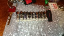
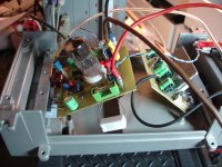
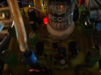
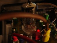
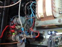
The first version up and running!
+/-44v (last photo is the power supply)
filaments:stabilized 12v d.c.
+/-44v (last photo is the power supply)
filaments:stabilized 12v d.c.
Attachments
Last edited:
- Status
- This old topic is closed. If you want to reopen this topic, contact a moderator using the "Report Post" button.
- Home
- Amplifiers
- Solid State
- Very Simple Hybrid Ampifier