OPS is tested with my earlier Low TIM Hybrid IPS
OK, attached the OPS to the heatsink, hooked up the Low TIM Hybrid IPS and gave it a try. Initial power-on showed stable low-volume oscillation at 5.38 MHz. Well, rather expected. 220pF caps between the gates and the drains of 2SK1058s solved the problem. Later on I have also increased the gate stoppers'value up to 470R in order to optimize the fast fronts response.
Load is 8R resistor.
Attached are the live measurements in the following order:
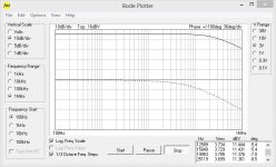
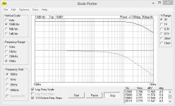
1) Bode plot for Low TIM Hybrid IPS (no OPS);
2) Bode plot together with the new OPS;
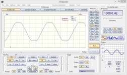
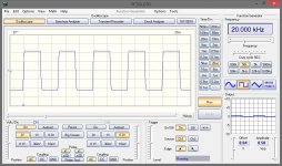
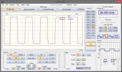
3) 20KHz 70V amplitude square wave responce (no OPS);
4) 20KHz 13V amplitude square together with OPS (reduced for keeping the load not too hot);
5) Clipping of the IPS alone (need much more powerful 8R for testing with the loaded OPS)
6) Updated schematic;
7) Updated PCB layout picture.
Some spectrums - in the next post.
OK, attached the OPS to the heatsink, hooked up the Low TIM Hybrid IPS and gave it a try. Initial power-on showed stable low-volume oscillation at 5.38 MHz. Well, rather expected. 220pF caps between the gates and the drains of 2SK1058s solved the problem. Later on I have also increased the gate stoppers'value up to 470R in order to optimize the fast fronts response.
Load is 8R resistor.
Attached are the live measurements in the following order:
1) Bode plot for Low TIM Hybrid IPS (no OPS);
2) Bode plot together with the new OPS;
3) 20KHz 70V amplitude square wave responce (no OPS);
4) 20KHz 13V amplitude square together with OPS (reduced for keeping the load not too hot);
5) Clipping of the IPS alone (need much more powerful 8R for testing with the loaded OPS)
6) Updated schematic;
7) Updated PCB layout picture.
Some spectrums - in the next post.
Attachments
-
 01 Bode - no OPS.JPG69.8 KB · Views: 1,269
 -
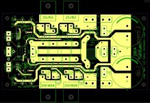 04 TubSuMo-OPS-pcb-FINAL.JPG252.9 KB · Views: 822
 -
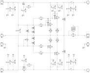 03 TubSuMo-OPS-sch-FINAL.jpg229.4 KB · Views: 725
 -
 01 sx Clipping 01KHz.JPG136.7 KB · Views: 1,128
 -
 01 SQR 20KHz 02.JPG138.4 KB · Views: 1,150
 -
 01 SQR 20KHz 01.JPG144.7 KB · Views: 1,201
 -
 01 Bode - OPS.JPG69.8 KB · Views: 1,225
Spectrums
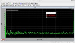
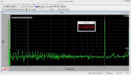
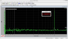
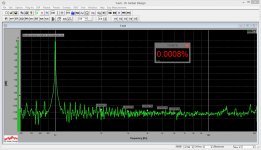
Here are the spectrums together with measurements in the following order:
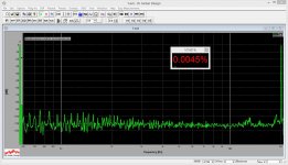
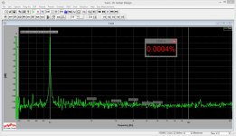
1) THD 1KHz 4.2V RMS - NO OPS
2) THD 1KHz 4.2V RMS - with OPS
3) THD 10KHz 4.2V RMS - NO OPS
4) THD 10KHz 4.2V RMS - with OPS
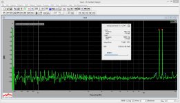
5) THD 20KHz 4.2V RMS - NO OPS
6) THD 20KHz 4.2V RMS - with OPS
7) IMD 14KHz + 15 KHz 4V RMS - with OPS
Listening - delicious, high resolution, dynamic, natural sound. Excellent elastic low-distortion bass. In fact, very close to the other OPS with 3-5 pairs of IRFPs and EF drivers, based on SlewMonster - well, pretty much ensured by IPS.
Waiting for ksc1845/ksa992 transistors for testing the new IPS...
The new one has got extra 6db of loop gain, plus at least twice as much of VAS current. Will be interesting")
Cheers,
Valery
Here are the spectrums together with measurements in the following order:
1) THD 1KHz 4.2V RMS - NO OPS
2) THD 1KHz 4.2V RMS - with OPS
3) THD 10KHz 4.2V RMS - NO OPS
4) THD 10KHz 4.2V RMS - with OPS
5) THD 20KHz 4.2V RMS - NO OPS
6) THD 20KHz 4.2V RMS - with OPS
7) IMD 14KHz + 15 KHz 4V RMS - with OPS
Listening - delicious, high resolution, dynamic, natural sound. Excellent elastic low-distortion bass. In fact, very close to the other OPS with 3-5 pairs of IRFPs and EF drivers, based on SlewMonster - well, pretty much ensured by IPS.
Waiting for ksc1845/ksa992 transistors for testing the new IPS...
The new one has got extra 6db of loop gain, plus at least twice as much of VAS current. Will be interesting
Cheers,
Valery
Attachments
-
 01 THD 20KHz 4VRMS 02.JPG196.6 KB · Views: 198
 -
 01 THD 20KHz 4VRMS 01.JPG193.7 KB · Views: 191
 -
 01 THD 10KHz 4VRMS 02.JPG197.5 KB · Views: 193
 -
 01 THD 10KHz 4VRMS 01.JPG192.7 KB · Views: 226
 -
 01 THD 01KHz 4VRMS 02.JPG198.1 KB · Views: 258
 -
 01 THD 01KHz 4VRMS 01.JPG196.2 KB · Views: 559
 -
 02 IMD 14-15KHz 4VRMS.JPG199.1 KB · Views: 201
Couple of observations
Just listened to Pink Floyd's "Mama" (from "The Wall") at the volume, where I can confidently feel the bass with my stomach Perfect! Ocean of sound, still with lots of micro-nuances and great instruments/voices separation.
Another observation - rock stable output pairs' quiescent current. After switching on, it goes up, then, within a minute, goes slightly down and settles at 90mA per pair. That's it. No fluctuations, that I can usually see in the designs with the spreader. Not even small ones. Amazing...
I like Lat-Fets more and more
Just listened to Pink Floyd's "Mama" (from "The Wall") at the volume, where I can confidently feel the bass with my stomach
Perfect! Ocean of sound, still with lots of micro-nuances and great instruments/voices separation.Another observation - rock stable output pairs' quiescent current. After switching on, it goes up, then, within a minute, goes slightly down and settles at 90mA per pair. That's it. No fluctuations, that I can usually see in the designs with the spreader. Not even small ones. Amazing...
I like Lat-Fets more and more
No fluctuations, that I can usually see in the designs with the spreader. Not even small ones. Amazing...
I like Lat-Fets more and more
Don't blame the bias spreader, it is the laterals that don't need the spreader.
Still I suggest to use a spreader here too just don't thermally connect with the laterals, it is safer as bad trimmer contact will not provoke the bias current to jump high, JLH school.
Hi Valery,
Looking very interesting! Do you think values will change in the OPS once the higher output IPS is attached? Also, did you need to match the outputs? I know on my ESP P101 it was highly recommended that the pairs be matched.
Thanks, Terry
Hi Terry,
No value change expected for IPSs with higher VAS current - R1 will allow to set the bias properly.
I did not do any matching - in this case you may have 2-nd harmonic a little bit higher than in case of matched ones, but a) with such a high loop gain, as we have here, difference will be rather low, and b) 2-nd harmonic is not "dangerous" for sonic impression, especially is its still at around -100db' level
With higher VAS current, I expect THD20 to be even lower, than you can see now.
Cheers,
Valery
vzaichenko
Great job!!.
Looks like VAS is doing the job well, the latfets are very nice and easy to drive.
Can you do the same measurements with e.g. 50V p-p please ?
I am thinking about making the one with the vacuum tubes at the input.
Can You tell me If the anode voltage has to be so high ? (100V) How abut use the tubes with low anode voltages - around 40V ??
Thanks
Peter
vzaichenko
Great job!!.
Looks like VAS is doing the job well, the latfets are very nice and easy to drive.
Can you do the same measurements with e.g. 50V p-p please ?
I am thinking about making the one with the vacuum tubes at the input.
Can You tell me If the anode voltage has to be so high ? (100V) How abut use the tubes with low anode voltages - around 40V ??
Thanks
Peter
Ummm... Peter, where do you see 100V? Actual anode voltage in this design is only 26V. Power supply is +/-70V and no other supplies required except 6.3V AC for heating.
Also, please note, the above tests are performed with different IPS module (Low TIM Hybrid) - I cannot test the new one as I'm still missing ksc1845/ksa992 transistors. So this is OPS test only, with known IPS, having wittingly good performance (I have mentioned this in post #61).
I cannot run these tests at 50V p-p at the output, as it gives us around 35V RMS, which is close to 150W at 8 ohm load - I don't have such a powerful load resistor at the moment. Testing with no load will show excellent results, so they don't make sense - it's the same as testing just IPS module.
If I manage to arrange a powerful load equivalent, I will run the tests at around 100W or so.
Cheers,
Valery
I bought one of these 300w 8R resistors. Works great. If you need to run it at wattage just drop in in a bucket of water. I keep meaning to buy a second so I can test at 4 ohms.
I bought one of these 300w 8R resistors. Works great. If you need to run it at wattage just drop in in a bucket of water. I keep meaning to buy a second so I can test at 4 ohms.
Terry, thanks for the link. I'm actually thinking of arranging some chassis-mounted ones on a heatsink... And a good input attenuator for the measurement system (at the moment it's a simple divider, allowing measurements at up to 4.2 V RMS).
LTspice for TubSuMo
Can you also provide the LTspice file for the tube version?
FET version has lower THD at 1kHz but higher THD at 20kHz.
Can you also provide the LTspice file for the tube version?
Just as an overall comment.
Unfortunatelyp), sonic quality is not just about THD. It depends on lots of parameters in certain combination, some compromises, etc. Most of high-loop-gain designs will show very good measurements. However, looking at a number of options with rather similar loop gain (and measurements), in most cases, the one will sound better, that is more linear with the loop open. Also, input stage capabilities to handle short term micro-overloads and gain distribution between the stages are important for keeping transient inter-modulation low (it's not purely about the slew rate!).
In these circumstances, tube at the input gives some clear advantages. Low noise, high linearity, excellent clipping behavior. Low TIM Hybrid showed less than 0.05% THD (1KHz, 4.2V RMS) open loop - measured on the live prototype. Closed loop IMD is also very low (that was one of the goals for that design). We'll see what this one is going to show, with slightly higher OLG.
I'm not saying there are no other ways of reaching the same sort of qualities.
This is just a relative easy (and, kind of, beautiful) way of doing it.
Cheers,
Valery
Unfortunately
p), sonic quality is not just about THD. It depends on lots of parameters in certain combination, some compromises, etc. Most of high-loop-gain designs will show very good measurements. However, looking at a number of options with rather similar loop gain (and measurements), in most cases, the one will sound better, that is more linear with the loop open. Also, input stage capabilities to handle short term micro-overloads and gain distribution between the stages are important for keeping transient inter-modulation low (it's not purely about the slew rate!).In these circumstances, tube at the input gives some clear advantages. Low noise, high linearity, excellent clipping behavior. Low TIM Hybrid showed less than 0.05% THD (1KHz, 4.2V RMS) open loop - measured on the live prototype. Closed loop IMD is also very low (that was one of the goals for that design). We'll see what this one is going to show, with slightly higher OLG.
I'm not saying there are no other ways of reaching the same sort of qualities.
This is just a relative easy (and, kind of, beautiful) way of doing it.
Cheers,
Valery
Last edited:
vzaichenko
Thanks for response.
I do not see here 100V anode voltage (in this design) but in most of designs it is as high as 100V (I am not sure what are the benefits --> better linearity ?)
If I can use the vacuum tubes at lower anode voltages it will be great. I will have to order the ''lamps'' first for test.
Thansk for hard work.
Peter
As the test load I am using this resistor:
100W 8 Ohm Non Inductive Resistor Power Amplifier Test Dummy Load | eBay
It can take a lot more than 100W for short period of time.
100W 8 Ohm Non Inductive Resistor Power Amplifier Test Dummy Load | eBay
It can take a lot more than 100W for short period of time.
vzaichenko
Thanks for response.
I do not see here 100V anode voltage (in this design) but in most of designs it is as high as 100V (I am not sure what are the benefits --> better linearity ?)
If I can use the vacuum tubes at lower anode voltages it will be great. I will have to order the ''lamps'' first for test.
Thansk for hard work.
Peter
Ah, I see what you mean
12AU7 (ECC82) is one of the tubes, working well at rather low voltages...
As the test load I am using this resistor:
100W 8 Ohm Non Inductive Resistor Power Amplifier Test Dummy Load | eBay
It can take a lot more than 100W for short period of time.
That is cheaper than the one I use. At that price you can afford to buy two so you can run 4 ohms. Mine is 300W though. I've put that much through it with a couple of my bigger amps. It needed to be submerged in a pail of water for that. Still, your costs half what mine cost. The surface mount resistors cost twice what mine cost. Very handy to have around. I'm sure they have saved many a speaker, not to mention. ear drums.
Terry.
There is another adventage of big resitors, you can put them in the kettle, set some nice square wave at input of the big amplifier and after 10min you can make a cup of cofee
Valery
I have ordered 12AU7 tubes and sockets, this will be my first try with the vacum tubes.
Hopefully I will not blow too many parts heh.
- Home
- Amplifiers
- Solid State
- Ultra-high performance, yet rather simple - hybrid and more!