Well I already ordered a 30 amp protection board off ebay, actually two, one for my flame linear 400... but that uses a 10 Amp relay- been anxious for their arrival... This will do all the functions you said above (Short, over, and spk prot.), but it will only operate and LATCH at absolute max conditions. You physically need to unplug the amplifier to reset the protection, its not as easy as cycling the power switch. This also switches the soft start circuit off, hence turning off the main power supply- I know this wont really protect anything within the amp should something go wrong...
Anyhow what is the purpose of replacing the resistor bridge with a resistor and diode you drew above?
Anyhow what is the purpose of replacing the resistor bridge with a resistor and diode you drew above?
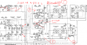
Here is the circuit I was talking about. This amp series have NO VI limiters on it, instead they use the UPC1237 to protect them. This is capable to 1 ohm- WOW- and uses LOW voltage rail at that setting...
This pushes 800W at 2 Ohm, so its not far off of my amplifier....
I labeled some things on it.
1= Main protection. Handles Spk relay DC offset, Overload, AC detect, Delay.
2= Voltage relay switch. IE, when too much current is driven to it it will switch the voltage to a lower rail via relay.
3= Overload circuit for the spk protection
4= Overload circuit for High/Low Voltage switching...
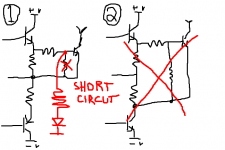
*Notice they used both sides to check it- however they still add the resistor and diode to ground as did you add to my circuit in post 41.
But what is the function of the diode and resistor to ground? to protect the transistor?
This pushes 800W at 2 Ohm, so its not far off of my amplifier....
I labeled some things on it.
1= Main protection. Handles Spk relay DC offset, Overload, AC detect, Delay.
2= Voltage relay switch. IE, when too much current is driven to it it will switch the voltage to a lower rail via relay.
3= Overload circuit for the spk protection
4= Overload circuit for High/Low Voltage switching...
*Notice they used both sides to check it- however they still add the resistor and diode to ground as did you add to my circuit in post 41.
But what is the function of the diode and resistor to ground? to protect the transistor?
Attachments
Last edited:
Yes, in this scheme, there is no limitation current.
The remaining parts are elements of standards of protection.
There's also a load sensor 4 or 8 Ohm.
Why do I need a diode and resistor.
This dynamic divider sensor base voltage of the transistor. If output short circuit, then a diode is locked, and the divisor is not working. This leads to the threshold of 0.7V operation of the sensor. This tripping current minimum.
If hard is no short, then the threshold of the sensor response becomes greater as the voltage output growth - is unlocked and running diode divider of two resistors.
This scheme is a good description of the output transistor in SOA
Posts 38 and 40 seem to misundertsand what the protection systems can detect and what protection they can offer.
One can detect Current and trigger on reaching a predeterimined value.
Or one can detect Current and Voltage and on reaching a predetermined IV value trigger on the protection.
How does one determine a short circuit?
Once a detection level has been reached, the protection can cut off the excessive I or IV, or one can limit at some particular maximum safe value.
Hi,
I used the ACS7XXX to protect my speakers using a micro. Why you do not use the hall effect ACS7XX to read the speaker current for overload? The problem with the ACSXXX you need a micro or a circuit using components to allow you to use the UCP1237 logic. The ACS7xxx will read +/- current and will protect the speaker in case of short. It is a simple way to read current and the most important issue it is do not interfered with the output sound. Also it is easy to install in the amplifier. just cut the amplifier out wire and install it before go out to the terminal.
I used the ACS7XXX to protect my speakers using a micro. Why you do not use the hall effect ACS7XX to read the speaker current for overload? The problem with the ACSXXX you need a micro or a circuit using components to allow you to use the UCP1237 logic. The ACS7xxx will read +/- current and will protect the speaker in case of short. It is a simple way to read current and the most important issue it is do not interfered with the output sound. Also it is easy to install in the amplifier. just cut the amplifier out wire and install it before go out to the terminal.
Hi,
I used the ACS7XXX to protect my speakers using a micro. Why you do not use the hall effect ACS7XX to read the speaker current for overload? The problem with the ACSXXX you need a micro or a circuit using components to allow you to use the UCP1237 logic. The ACS7xxx will read +/- current and will protect the speaker in case of short. It is a simple way to read current and the most important issue it is do not interfered with the output sound. Also it is easy to install in the amplifier. just cut the amplifier out wire and install it before go out to the terminal.
I used the ACS7XXX
Excellent solution , I read the Allegro documentation..
Some are DC only (rails) , some can do AC. They have the option of analog
or I2C outputs. Either can be used in a Arduino protection scheme.
But , for the 1237 ... you would have to scale an analog sensor to some
R/C timed comparator. Easier to go the full micro route with A/D polling.
OS
Hi,
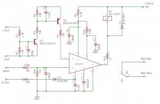
Attached it is an schematic for those that does not want to use a micro. The circuit it is designed using components to read the ACS78XX and trigger a f/f to disable the speaker when reach the current setting limit set by R1/R3 . The current setting limits are set by resistors R1 for the positive current and the R3 for the negative. R2 represent the ACS78XX in the circuit. I am using two op amp comparators for determine the current limits. The f/f it is reset unconditionally on power ON by holding the clear side of the f/f for a short time. If the +/- current reached the current setting it will unconditionally set the f//f by grounding the set side of the f/f and it will disable the speakers. To reset you use the switch or turning off the circuit. As you can see it is a simple circuit using the hall effect sensors and you can buy the current modules for less than 4.00 dls in Ebay for the 5 amps current. There are current sensors available for 5,12 , 20, 30, 50, 100, and 200 amps.You need to buy the one for +/- current. In the circuit I used a relay for simplicity but you can use a SSR. Also the schematic shown on channel only.
Attached it is an schematic for those that does not want to use a micro. The circuit it is designed using components to read the ACS78XX and trigger a f/f to disable the speaker when reach the current setting limit set by R1/R3 . The current setting limits are set by resistors R1 for the positive current and the R3 for the negative. R2 represent the ACS78XX in the circuit. I am using two op amp comparators for determine the current limits. The f/f it is reset unconditionally on power ON by holding the clear side of the f/f for a short time. If the +/- current reached the current setting it will unconditionally set the f//f by grounding the set side of the f/f and it will disable the speakers. To reset you use the switch or turning off the circuit. As you can see it is a simple circuit using the hall effect sensors and you can buy the current modules for less than 4.00 dls in Ebay for the 5 amps current. There are current sensors available for 5,12 , 20, 30, 50, 100, and 200 amps.You need to buy the one for +/- current. In the circuit I used a relay for simplicity but you can use a SSR. Also the schematic shown on channel only.
Attachments
Posts 38 and 40 seem to misundertsand what the protection systems can detect and what protection they can offer.
One can detect Current and trigger on reaching a predeterimined value.
Or one can detect Current and Voltage and on reaching a predetermined IV value trigger on the protection.
How does one determine a short circuit?
Once a detection level has been reached, the protection can cut off the excessive I or IV, or one can limit at some particular maximum safe value.
Alright, so I am using the current through the output emitter resistors to calculate the current going to the speaker, or to make it simple- the current going through the output resistor then monitoring the voltage potential across this. I am looking for the most primitive, cheapest, and simplest way to do this. I have no intentions of putting a micro in the amplifier. A UPC1237 is on the way with two 30 amp relays (It was actually suppose to arrive by now).
P=IV V=IR
Therefore V = sq(P(R)) where sq() is the square root.
SO:
Max power (1000W) into 2 ohms-
V= sq(P(R))
V= sq(1000W(2)) = sq(2000) = 44.72 volts.
Therefore I need 44.72 volts to go to the speaker at~
V / R = I
44.72volts/2ohms= 22.36Amps
SO calculating voltage across .22 ohm emitter resistor-
22.36Amps / 8 output transistors = ~2.79 amps per transistor.
I * R = V
SO 2.79amps across .22 ohms is 0.6138 volts across the emitter resistor
Max power (1000W) into 4 ohms-
V= sq(P(R))
V= sq(1000W(4)) = sq(4000) = 63.24 volts.
Therefore I need 63.24 volts to go to the speaker at~
V / R = I
63.24 volts/4 ohms= 15.81 Amps
SO calculating voltage across .22 ohm emitter resistor-
15.81 Amps / 8 output transistors = ~1.88 amps per transistor.
I * R = V
SO 1.88amps across .22 ohms is 0.4136 volts across the emitter resistor
I hope we agree with all above. I know that a speaker is not perfect, that is, its impedance not a constant resistance.
Based on all of that, I simply need a circuit that will sense +/- .8 volts across both positive and negative emitter resistors. .8 volts should allow ample room for the amplifier to hit 1000 watts in 2 ohms.
In a short circuit voltage will swing high (or low)- to full supply rail voltage (around +/-80v). This will be sensed by the circuit that watches the voltage across the emitter resistors. Since the voltage is much greater than .8 volts, the amplifiers output will be switched off. Assuming the short is not in the amplifier (before the relay), it should be able to break it in time.
Now because the threshold for the protection is so great, I opted to completely shut down the amplifier as well.
The protection will trip in with one of the three problems overheat, overload, or DC on the speakers. Primarily the speakers will be tripped out, but the main power transformer will be cut out too, as well the fan will go high. To reset the amp you will have to unplug it from the wall and plug it back in.
At least that's what I comprehend? 😕
You are monitoring current by measuring the Vdrop.Alright, so I am using the current through the output emitter resistors to calculate the current going to the speaker, or to make it simple- the current going through the output resistor then monitoring the voltage potential across this. I am looking for the most primitive, cheapest, and simplest way to do this. I have no intentions of putting a micro in the amplifier. A UPC1237 is on the way with two 30 amp relays (It was actually suppose to arrive by now).
P=IV V=IR
Therefore V = sq(P(R)) where sq() is the square root.
SO:
Max power (1000W) into 2 ohms-
V= sq(P(R))
V= sq(1000W(2)) = sq(2000) = 44.72 volts.
Therefore I need 44.72 volts to go to the speaker at~
V / R = I
44.72volts/2ohms= 22.36Amps
SO calculating voltage across .22 ohm emitter resistor-
22.36Amps / 8 output transistors = ~2.79 amps per transistor.
I * R = V
SO 2.79amps across .22 ohms is 0.6138 volts across the emitter resistor
That gives you current detection.
Voltage is not is detected and so power detection cannot be implemented.
You are effectively detecting and triggering on a current level.Max power (1000W) into 4 ohms-
V= sq(P(R))
V= sq(1000W(4)) = sq(4000) = 63.24 volts.
Therefore I need 63.24 volts to go to the speaker at~
V / R = I
63.24 volts/4 ohms= 15.81 Amps
SO calculating voltage across .22 ohm emitter resistor-
15.81 Amps / 8 output transistors = ~1.88 amps per transistor.
I * R = V
SO 1.88amps across .22 ohms is 0.4136 volts across the emitter resistor
I hope we agree with all above. I know that a speaker is not perfect, that is, its impedance not a constant resistance.
Based on all of that, I simply need a circuit that will sense +/- .8 volts across both positive and negative emitter resistors. .8 volts should allow ample room for the amplifier to hit 1000 watts in 2 ohms.
In a short circuit voltage will swing high (or low)- to full supply rail voltage (around +/-80v). This will be sensed by the circuit that watches the voltage across the emitter resistors. Since the voltage is much greater than .8 volts, the amplifiers output will be switched off. Assuming the short is not in the amplifier (before the relay), it should be able to break it in time.
Now because the threshold for the protection is so great, I opted to completely shut down the amplifier as well.
The protection will trip in with one of the three problems overheat, overload, or DC on the speakers. Primarily the speakers will be tripped out, but the main power transformer will be cut out too, as well the fan will go high. To reset the amp you will have to unplug it from the wall and plug it back in.
At least that's what I comprehend? 😕
Have a read of Leach's explanation of current limiting in his Lo Tim papers.
On a fast rise time signal that continues to exceed your current set point, your output devices may have exploded before you have triggered your protection and then you have to activate the switch that implements the protection.
You could read Bonsai's explanation of a fast Solid State relay detection and trigger system. It's in his NX paper. This addresses detection and triggering that is fast enough to protect a fast rise time signal that should protect before the output devices overload.
Last edited:
max voltage on pin 1 ...
Hello,
I want to add overpower protection on pin 1 ... it is external schematic to monitor the output power by lm3915 ... and from desired output led will try to pass it to pin 1 on UPC1237 ....
Can you tell me the MAX voltage that I can put to pin 1 on UPC1237 ... ?
and MIN voltage too ???
Thank you in advance -
Emil
Hello Emil
In uPC1237 pin 1 come overload the current data(short pulse).
This short pulse overload LM3915 will not be able to display this.
Use the chip according to the datasheet.
In uPC1237 pin 1 come overload the current data(short pulse).
This short pulse overload LM3915 will not be able to display this.
Use the chip according to the datasheet.
?
Hi,
What will happen if pin 1 is connected to 1V DC .... for 10 second ...UPC1237 will burn ??
Can someone tell me the max voltage that can be pass to pin 1 ?
Regards,
Emil
Hi,
What will happen if pin 1 is connected to 1V DC .... for 10 second ...UPC1237 will burn ??
Can someone tell me the max voltage that can be pass to pin 1 ?
Regards,
Emil
Here's the overcurrent detection circuit we use in the 21'st Century Protection systems adapted to work with the uPC1237. It measures the voltage drop across a pair of emitter resistors for current sensing. Pin 1 of J5 goes to the emitter side of a positive emitter resistor, pin to goes to the emitter side of a negative resistor. With the listed components it will trigger around 2VDC which works out to 4.4 amps on a pair of 0.22R emitter resistors. The overload detection circuits have been tested, but the conversion to the uPC1237 still needs to be live tested, but I don't have one to prototype so I can't do it myself. Some resistance values may need to change.
Attachments
Last edited:
Hi,
What will happen if pin 1 is connected to 1V DC .... for 10 second ...UPC1237 will burn ??
Can someone tell me the max voltage that can be pass to pin 1 ?
Regards,
Emil
Pin 1 doesn't care about voltage, it needs to be current limited to 3mA max. It looks like it's much like feeding the base of a transistor from the datasheet. Divide whatever voltage you are feeding to it by .003 (3mA) to figure out the minimum resistance you need to put in series with it.
Series resistor 22-47kOm for pin1 uPC1237 - garantied not burn chip.Hello,
I want to add overpower protection on pin 1 ... it is external schematic to monitor the output power by lm3915 ... and from desired output led will try to pass it to pin 1 on UPC1237 ....
Can you tell me the MAX voltage that I can put to pin 1 on UPC1237 ... ?
and MIN voltage too ???
Thank you in advance -
Emil
Here is what I have got so far, collecting pieces bit by bit. Some notes:
There are some open questions though...
- +OUT and -OUT go to the output stage transistors emitters
- ZERO goes to audio zero
- the schematic is for one channel
There are some open questions though...
- Does protection need to have its own transformer for +25VDC power or can it run from the main amp transformer? (my transformer has an unused extra secondary that I could use for the protection board)
- How good does the +25VDC need to be? May I use a rectifier bridge with a small cap, say 1000uF? Do I even need a cap?
- My understanding is that the relay is normally closed. Correct? If this is the case, how does this protection manage to achieve "power-on mute" (pin 7)? The relay will be closed and speaker connected at power-on. Does the relay open quicker than the audio shock propagates through the amp? I guess this could be the case due to the fact that PSU caps are much larger than the cap used in the protection board PSU and so charge longer. Right?
- ACOFF is a separate input to detect power off event and mute speaker. It should go to the main transformer secondary. My understanding is that you should not connect ACOFF to +25VDC for the reason that +25VDC will have a capacitor that holds charge and doesn't allow the IC to detect the event in a timely manner. Correct?
Attachments
Last edited:
- Home
- Amplifiers
- Solid State
- Overload detection circuit for UPC1237