Today, with LTspice, this strategy is probably as good as many.Just to try them all and pick the best isn't very sharp.
Have you any ideas about this?
About my most concrete 'recommendation' is I would use pure Cherry for a Blameless topology and I can get very good results for THD, stability bla bla.
But I'm sure many, with different favoured devices, operating points etc, will have different opinions.
I don't have sufficient (LTspice or analytical) experience with other topologies to pontificate on them ..
If you simplify stuff, eg single device VAS + EF2 stages or enhanced VAS + MOSFET (no drivers), I am on surer (real life) ground. Pure Cherry is better than TPC and in some cases, TP Cherry. No 1ppm 50W THD20k though.
The 'some cases' is cos these simpler topologies have insufficient LF gain to make TP Cherry worthwhile. I'm hoping to find some time to see if LTspice can replicate my experience with these
This was 'real life' from more than 20 yrs ago for a commercial project. I could dream up an LTspice example but that would be cheating. 😀I don't see why, for comparable stability when properly measured - that is, with the probe in the correct place for that feedback loop structure.
I suppose there are small differences in the shunt loads but I expect that to be very minor.
It's not a simple question, and our previous discussions still haven't properly sorted it out, I look forward to more. 😉
Do you have an example ASC where TP Cherry beats equivalent plain TPC?
Most of the stuff, I've been doing has been trying to get LTspice to replicate my Jurassic 'real life' experiences.
The reason why I've persevered with Self's Blameless (its not really my favourite) is cos astx has shown loadsa careful 'real life' measurements that help me confirm misty memories.
The level of discussion is such that to make further worthwhile (LTspice) contributions, I'd need to do a lot of work. But I'm happy to assume I have eidetic memory of Jurassic experience 🙂
Duu.uuh! I'm still in the dark.I think Paul means Double Transitional Miller Compensation, another of Edmond Stuart's acronyms.
Paul, got a link to something that shows or explains this?
Last edited:
Today, with LTspice...
This reminds me too much of "monkeys with typewriters" and Hamlet.
I want to understand and then it will be clear why one technique works better in a specific case.
"Two Pole schemes benefit from plenty of Loop Gain" for instance, is a rule that is simple but useful.
Probably why it's one where there is a consensus, I want to find more.
Duu.uuh! I'm still in the dark...
Come on, it's not that hard to search this forum for posts on "DTMC", in date order to see how it started and develops.
I just did it and even the first post pretty much explains the idea.
Best wishes
David
Last edited:
Thanks you too, JCX. It was a pretty abstract read, but I did make connections to what we're doing with audio 🙂
--
I've also figured out what was my problem with the Bode plot. I was totally being stupid. Depending on how the HEC is tuned, the phase will go the other direction and numbers stopped making much sense. However, wrapping the phase showed that the phase makes a 360 but then goes back to 'normal'.
I was able to get to improve the HEC bandwith and overall speed and stability. Both short circuiting and clipping show well defined behaviour, from IPS to VAS to HEC to OPS, no ringing or going into oscillations. Squares are a bit malformed, but that's because of my HEC current limiters that also serve as a stabilizer for when the HEC is overdriven or comes back from recovery. This only happens during slew limiting. It cost me some THD, but still, the numbers are still the best I've been able to achieve for the given power: 20K/500W/4R yields 0.000023%THD 😀 I think it's a testimony to the performance of the front-end.
It appears that the Tian probe is still accurate even with the more complex combination of the HEC inside GNFB, and no, I didn't have it in the wrong location (wew).
It's more, "Two pole schemes only show advantage with loadsa Loop Gain".This reminds me too much of "monkeys with typewriters" and Hamlet.
I want to understand and then it will be clear why one technique works better in a specific case.
"Two Pole schemes benefit from plenty of Loop Gain" for instance, is a rule that is simple but useful.
Probably why it's one where there is a consensus, I want to find more.
I don't think its a case of "this works better for this".
More feedback is always better .. if (and its a very big IF) the whole shebang is 'stable'. It's more like "why is this topology unstable when I use pure Cherry?"
I like very simple topologies cos there's a small chance of doing proper analysis. Slightly more complex and its back to da monkeys 🙂
There's also subtle issues like making the VAS output HiZ (as with pure Cherry) to reduce xover & high order harmonics.
There's loadsa proposed (and built) supa complex circuits on diyaudio which show little or no sign of a full stability analysis .. apart from a cursory glance at PM & GM.
I list what I do in LTspice (and real life) to check stability on the 'TPC vs TMC vs pure Cherry' thread.
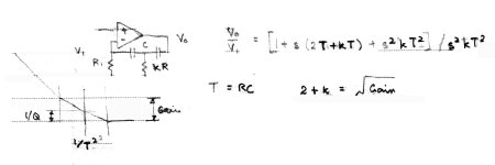
Analysis gives insight .. usually after the 'real life' circuit exhibits something unexpected.
But as evidence that I kan reed en rite, here's an analysis I did circa 1980 to help design TPC.
Du.uuh! Xcus 1 hu kunt reed en rite 😱Come on, it's not that hard to search this forum for posts on "DTMC", in date order to see how it started and develops.
I just did it and even the first post pretty much explains the idea.
And I'm not sure that TMC & DTMC come under the monkeys too.
kgr(monkey)lee
Attachments
Last edited:
I guess you can say that because my experience is that LOLG (loads-of-loop-gain) basically requires two-pole schemes because otherwise gain will never go below unity before the whole thing goes wonk. (Apart from 1st order phat millers defeating the whole purpose of LOLG)It's more, "Two pole schemes only show advantage with loadsa Loop Gain".
. From what I have read [the GFT probe] shows compared to the basic Middlebrook and Tian probe differences...
...stabilty problems which are not revealed by the previously mentioned probes
I just remembered that I didn't answer this completely.
There are differences between the Middlebrook GFT and both the earlier, simple Middlebrook (1975) and Tian.
But I said I did not think those differences were the reason stability problems were not revealed.
In fact Frank Wiedmann says there is no difference in the stability predictions of the three probes, all correctly predict whether an amp is stable or not.
I haven't checked this but presumably the terms that cause the difference are cancelled or null at the ULGF and the differences only occur elsewhere.
Best wishes
David
Is it a reasonable assumption that TP-MIC can equal the performance DTMC with the same stability? With both schemes optimised.
I said that I was satisfied with TP-MIC and so had not really considered DTMC.
I mulled this over a bit since you asked the question.
First question is whether it is practical to separate the front-end and back-end connection schemes.
So, can the front-end scheme, either MIC or IPS-to-VAS-Transitional (to coin a clumsy term) be independently combined with the back-end scheme, either TPC or TMC?
There seems to be the possibility of unexpected interactions, similar to the way HEC interacts with the Global feedback.
But if we can consider the front and back schemes in isolation.
We have already discussed the TMC v TPC a bit.
For the front end comparison there are several issues.
First, remember that to view TMC as a "transitional" scheme actually mislead people away from the way it really works, as a Two Pole scheme.
Similarly the "transitional" front end adds an extra parameter, a time constant, over MIC.
That extra time constant at a minimum makes analysis more complicated, and probably makes the stability more likely to be only conditional.
The second issue is that it is better to have an overall loop than two consecutive loops, if stability allows.
It seems MIC should be preferable on that basis.
Finally, in a complementary IPS like mine, there is an incentive to avoid two separate feedback points (the two VAS inputs in the transitional scheme) and have just one (the IPS for MIC).
So prima facie I think MIC looks not only equal but better.
Best wishes
David
Last edited:
I said that I was satisfied with TP-MIC and so had not really considered DTMC.
I mulled this over a bit since you asked the question.
First question is whether it is practical to separate the front-end and back-end connection schemes.
So, can the front-end scheme, either MIC or IPS-to-VAS-Transitional (to coin a clumsy term) be independently combined with the back-end scheme, either TPC or TMC?
There seems to be the possibility of unexpected interactions, similar to the way HEC interacts with the Global feedback.
But if we can consider the front and back schemes in isolation.
We have already discussed the TMC v TPC a bit.
For the front end comparison there are several issues.
First, remember that to view TMC as a "transitional" scheme actually mislead people away from the way it really works, as a Two Pole scheme.
Similarly the "transitional" front end adds an extra parameter, a time constant, over MIC.
That extra time constant at a minimum makes analysis more complicated, and probably makes the stability more likely to be only conditional.
The second issue is that it is better to have an overall loop than two consecutive loops, if stability allows.
It seems MIC should be preferable on that basis.
Finally, in a complementary IPS like mine, there is an incentive to avoid two separate feedback points (the two VAS inputs in the transitional scheme) and have just one (the IPS for MIC).
So prima facie I think MIC looks not only equal but better.
Best wishes
David
Been looking a little more closely at DTMC and started working on a TP-MIC version of my amp. So far there appears to be an initial advantage of DTMC or a at least a feature of it.
Bootstrapping the CMLC compenstaion to a replica (driven from the amplifier output) of the signal seen at the IPS feedback point appears to bring a large increase in stability for the VAS loop. Choose to use a replica in the TP-MIC version so as to reduce loop interation. Not analysed this in any detail yet but you do see affects on the shape and magnitude of the "HEC bode step".
DTMC does have some subtleties that go against what you would expect to see.
Going to keep working at the TP-MIC version of my amplifier to see if it can match (or beat) the "transitional" version but I have to agree that there is, in all probability, more to DMTC than meets the eye...
Paul
P.S. Kgrlee - http://home.tiscali.nl/data.odyssey/PMP.html for a little on DTMC.
... multi loop systems...
To the extend that I am aware of, there are a few methods...
Thanks for the proper reference to the Hurst paper that I mentioned earlier, it deserves to be more widely read.
Some published nested loop analyses are based around the simplified loop model with strictly one-way transmission.
This is precisely the simplification that the GFT analysis is intended to supersede.
I need to check this in Hurst, have you considered this or have any references?
Another typical example that I am sure many DIYers encountered is an output stage (triple, CFP) instability which is not shown in the global loop stability analysis but which can be a blue smoke generator...
I have taken more or less this position in a debate with Richard Lee but now I am not so sure.
I suspect practice has more to do with unmodelled parasitics and non linearities than a theoretical weakness in the analysis.
As soon as we have oscillations then non-linearities are all that stops the system from infinities, so the linear model fails.
Any useful ideas or references?
... sequential loop closure (SLC). It involves ...
Therefore, I believe that Hurst criteria are [all] we need...
Yes I also believe the SLC method is irrelevant to audio and Hurst (or GFT extension?) is adequate.
Best wishes
David
Last edited:
Hi David,
Time to revive this 5* thread 😉
My conclusion is that DTMC and the CMCL are made for each other. It does not appear to be possible to compensate without using the resistor R20. Without R20 the VAS loop does not have good stability. Good stability can be achieved if you slow the VAS loop down enough. It even appears the CMCL is not happy without R20.
My attempt at TP-MIC failed miserably. Got ok stability margins and equal THD20K but the slew rate was terrible.
Also, I don't find that DTMC doesn't give the same benefit without the CMCL. But this could down to my unscientific approach.
It would be interesting to setup some LTSpice test jigs to compare the different forms of compensation. Just need to come up with a simple consistent method of comparison.
Paul
P.S. Have taken on your thoughts about getting equal performance from simpler designs. 😉 http://www.diyaudio.com/forums/solid-state/265449-amp-designed-during-lunch-breaks.html
My conclusion is that DTMC and the CMCL are made for each other. It does not appear to be possible to compensate without ... resistor R20.
R20 where? which post exactly?
...to compare the different forms of compensation. Just need to come up with a simple consistent method of comparison.
I have done a little calculation on nested loops and now understand this better.
I am now fairly clear on just where to probe to analyse the stability in a consistent way.
So if we have ASCs then we can compare them pretty well.
That should help us reconcile my expectations from theory with your experiments, should be educational.
Best wishes
David
Last edited:
R20 where? which post exactly?
Hi David,
http://www.diyaudio.com/forums/solid-state/261973-middlebrook-gft-probe-7.html#post4086684
Planning to use this schematic as the basis of any investigation.
I have done a little calculation on nested loops and now understand this better.
I am now fairly clear on just where to probe to analyse the stability in a consistent way.
So if we have ASCs then we can compare them pretty well.
Best wishes
David
You do calculations. I'm still at the concept level 😉
Will post the ASC I have from my primitive investigation later on when I get home.
Any conclusions can be implemented in reality. Add credibility... Have spent ages organising my components so prototypes should be much quicker to build.
Paul
P.S. Still very interested in this. Just had a period of insomnia. Can't really function when those periods happen. Still much to learn...
...use this schematic as the basis
That is actually a very awkward scheme to analyse.
There is a MIC loop (C4+C16, R20), an OIC loop (C15+C21, R48, R4), a Miller loop (C15+C21,R48, C7, C4 + C16) and Lead compensation on the overall feedback (R4, C7, R20).
All mixed up, about as complicated as a 3 section amp can be.
We usually assume one way loop transmission for simplicity but here that will be totally inadequate.
The bi-lateral transmission is precisely the sort of situation that does require a GFT probe to handle, but a bit too much of a jump in the deep end, I feel.
That's not to even mention the HEC OPS where bilateral transmission is also a major issue.
I was chuffed just to understand that. As far as I can tell that's actually better than Hawksford himself.😉
Best wishes
David
Agreed. It is very complicated but it does work. And I can't see how the CMCL can be compensated in a less complicated way. It's enlightening to increment the component values to see the changes. You see relationships that are not immediately apparent. This leads me to believe that there is more to this than I understand.
It would be good to isolate the VAS stage and use ideal IPS and OPS. The problem I have is how to represent the HEC. Maybe replace with a non corrected scheme for investigations?
Would like to investigate the compensation of a plain CFA IPS to VAS connection, Edmond's CMCL and a current mirror linked CFA IPS and OPS. Is this too adventurous?
This seems to relate well with your Linear Audio Articles. When's part 3 due?
Wish I was as knowledgeable as yourself. The GFT probe is still illusive. Probably a good thing as I have many more concepts to understand. You are right to be chuffed. 🙂
Paul
... And I can't see how the CMCL can be compensated in a less complicated way....
The CMCL, ideally, should not interact with the compensation at all.
So it would not require the compensation to be more complicated.
In my MIC + CMCL test model that is pretty much the case.
I remember that in your implementation there was some interaction that I initially overlooked because I was lead astray by expectations based on my own version.
Just can't remember the details off hand, do you recall the thread we discussed this?
...and use ideal IPS and OPS. The problem I have is how to represent the HEC. Maybe replace with a non corrected scheme
I am really a fan of "start simple" and then add complexity only when you deeply understand a level.
HEC looks very dubious to me, at best unnecessary and possibly counter-productive.
...This seems to relate well with your Linear Audio Articles. When's part 3 due?
I hope next issue. I skipped the current issue because I felt there was more to do before I really understood the next step.
I believe that was the correct decision, I have learned important information. But I still have to write the actual article😉
Thanks for the kind words, I sure don't feel like an authority.
I just think the best way to learn a subject is to try to explain it.
That teaches me what I need to understand.
Best wishes
David
The CMCL, ideally, should not interact with the compensation at all.
So it would not require the compensation to be more complicated.
In my MIC + CMCL test model that is pretty much the case.
I remember that in your implementation there was some interaction that I initially overlooked because I was lead astray by expectations based on my own version.
Just can't remember the details off hand, do you recall the thread we discussed this?
I think it was this thread if my memory hasn't failed me.
http://www.diyaudio.com/forums/solid-state/261973-middlebrook-gft-probe-5.html#post4082176
I am really a fan of "start simple" and then add complexity only when you deeply understand a level.
HEC looks very dubious to me, at best unnecessary and possibly counter-productive.
HEC does allow the cheapest components to sound good. When it is within a NGFB loop, I not convinced either yet...
I hope next issue. I skipped the current issue because I felt there was more to do before I really understood the next step.
I believe that was the correct decision, I have learned important information. But I still have to write the actual article😉
Look forward to it. I feel like I'm left hanging. 😉 Will we see your "simple" CMCL?
Thanks for the kind words, I sure don't feel like an authority.
I just think the best way to learn a subject is to try to explain it.
That teaches me what I need to understand.
Best wishes
David
You write articles for Linear Audio.... 😉
IMHO, you know when you understand something when you can teach something in simple terms.
Really appreciate the knowledge you share. Thank you.
Paul
- Status
- Not open for further replies.
- Home
- Amplifiers
- Solid State
- Middlebrook "GFT" probe?