Excellent, thanks, did you ever do any more on this?
Paul's HEC amp looks like it has a fundamental "issue" and your plot of Bob's seemed to imply the same there, haven't reread the thread yet.
I am surprised no one else seems to have noticed this, or have I missed some reference?
Jan Didden's Pax amp uses a different technique for HEC and may not suffer the same concern, haven't looked closely yet.
Best wishes
David
Hi David,
What do you think of this EC? http://www.diyaudio.com/forums/solid-state/260308-gainwire-ngnfb-classb-poweramp.html
Best regards
Damir
Excellent, thanks, did you ever do any more on this?
Paul's HEC amp looks like it has a fundamental "issue" and your plot of Bob's seemed to imply the same there, haven't reread the thread yet.
I am surprised no one else seems to have noticed this, or have I missed some reference?
Jan Didden's Pax amp uses a different technique for HEC and may not suffer the same concern, haven't looked closely yet.
Best wishes
David
Yes, I would agree that my amp has a fundamental problem. Have simmed the amp with a 3EF and the loop plots from that were very educational. Have come to the conclusion I need a different OPS. Expected problems but not so fundamental. 😉
If I understand this issue correctly, it's not something that can be fixed by changing loop compensation. Needs a topology change...
The current prototype has been put away ready for any potential fix... But the project goes on.
Paul
some here might like to know Classical Feedback Control website is back with the Classical Feedback book frequency compensation chapter and the 2 appendices online
the archive.org copy was getting pretty ragged with many pics not there
the archive.org copy was getting pretty ragged with many pics not there
What do you think of this EC?...
Hi Damir
It's more complicated than I prefer so I haven't simulated it, but just from a look I think the FETs U1 and U3 should act as buffers to prevent feed forward.
And no global feedback should avoid the two loop interaction problem anyway.
So I expect there's no surprises.
Best wishes
David
Sheesh jcx 😱some here might like to know Classical Feedback Control website is back with the Classical Feedback book frequency compensation chapter and the 2 appendices online
the archive.org copy was getting pretty ragged with many pics not there
Wish I kud reed en rite 2 unnersten dis supa stuf 🙂
I grovel at your feet in awe.
beach bums don't do Calculus, Complex Variable Theory?
I haven't mastered all of Lurie's book, but he does give a different perspective on "Classical" frequency response methods that I've not seen elsewhere, I find valuable
would've thought avoiding body surfing salties, the poisonous just about everything would keep the mind sharp
I haven't mastered all of Lurie's book, but he does give a different perspective on "Classical" frequency response methods that I've not seen elsewhere, I find valuable
would've thought avoiding body surfing salties, the poisonous just about everything would keep the mind sharp
Last edited:
Most of dis hi falutin' stuff has little or no practical use.
The only such treatment I found useful was Prof Cherry's Feedback, Sensitivity and Stability of Audio Power Amplifiers
In the previous Millenium, wen eye kud steel reed en rite, I programmed his matrix treatment in Lotus 123.
IMHO, this detailed analysis is his greatest contribution to the SOTA of amp. design .. even more important than his NDFLs.
I've been 3.5m away from a 3.5m croc in a 3.5m kayak. I NEVER EVER want to be so close to a small croc. [1]would've thought avoiding body surfing salties, the poisonous just about everything would keep the mind sharp
[1] Queensland Parks & Wildlife's definition of "small croc" is : under 4m
Last edited:
Middlebrook's Design Oriented Analysis, GFT are an attempt to make human interpretable sense of circuits
few are designing audio circuits from the State Space Admittance Matrix - even if the State Space tools are useful for analysis after you've got a topology
let you apply Cherry's “ESTIMATES OF NONLINEAR DISTORTION IN FEEDBACK AMPLIFIERS” JAES V48#4 2000 p299-313 technique
few are designing audio circuits from the State Space Admittance Matrix - even if the State Space tools are useful for analysis after you've got a topology
let you apply Cherry's “ESTIMATES OF NONLINEAR DISTORTION IN FEEDBACK AMPLIFIERS” JAES V48#4 2000 p299-313 technique
"IMHO, this detailed analysis is his greatest contribution to the SOTA of amp. design .. even more important than his NDFLs."
I would said it was LTspice!
😀
I would said it was LTspice!
😀
I got hold of a paper a few years ago (can't remember where I put it) of the loop analysis of a complex servo system incorporating mechanics, optics etc.
Despite all the earnest engineering discussion and 'head wringing' on this website, audio amps still quality as 'simple control systems'.
I have Walter Hauseman's (sp?) ~1970's design report on the Saturn 5 rocket on my website (which is down right now). If you want to stretch the grey cells take a look at that - it is beyond me, but the aspects to consider from the control side are fascinating in my view.
Anyway, back to audio - I digress.
Middlebrook's Design Oriented Analysis, GFT are an attempt to make human interpretable sense of circuits
few are designing audio circuits from the State Space Admittance Matrix - even if the State Space tools are useful for analysis after you've got a topology
let you apply Cherry's “ESTIMATES OF NONLINEAR DISTORTION IN FEEDBACK AMPLIFIERS” JAES V48#4 2000 p299-313 technique
A functional topology is not really a problem, what is a nightmare is the number of loops once they are all closed, i really dont see how to do a proper analysis set apart for the usual global, loop gain and phase responses, actualy i end with some kind of black box whose only three ports caracteristics, that is +- inputs and output, out of six can be checked accurately.
... my amp has a fundamental problem. Have simmed the amp with a 3EF and the loop plots from that were very educational. Have come to the conclusion I need a different OPS. Expected problems but not so fundamental. 😉
If I understand this issue correctly, it's not something that can be fixed by...
The current prototype has been put away ready for any potential fix...
Hi Paul
I did say it was an "issue" rather than a problem, because I hadn't had the time to think about it.
It is certainly possible to do an excellent HEC amplifier, I simmed JCX's version of Bob's JAES amp and the results are still impressive. Bob presumably adjusted the amp based on real measurements because it looks just about spot on.
He seems to have arrived at experimentally optimum values that were better than the theory of the time would have calculated.
So a HEC OPS is still a viable option.
But the issue is feed forward in the Hawksford implementation. Even Hawksford himself seems not to have picked up on this, as far as I can tell. To optimize or circumvent that will require some work.
For a hi-fi amplifier it does seem there are simpler ways to achieve comparable results, unless you want to do it as a technical exercise.
I went back to Bode and found that it was all there, as usual, but I hadn't quite taken it in, as usual, I need a specific example and incentive.
Turns out Middlebrook's GFT probe relies on exactly the theory that Bode developed for this type of situation.
So now I see better how they connect, certainly an educational technical exercise for me so far, thanks😉.
Best wishes
David
P.S. Andrew, any luck with the low distortion CFA schematic?
Last edited:
Hi Paul
I did say it was an "issue" rather than a problem, because I hadn't had the time to think about it.
It is certainly possible to do an excellent HEC amplifier, I simmed JCX's version of Bob's JAES amp and the results are still impressive. Bob presumably adjusted the amp based on real measurements because it looks just about spot on.
He seems to have arrived at experimentally optimum values that were better than the theory of the time would have calculated.
So a HEC OPS is still a viable option.
But the issue is feed forward in the Hawksford implementation. Even Hawksford himself seems not to have picked up on this, as far as I can tell. To optimize or circumvent that will require some work.
Hi David,
I see it as problem in it's current state. The spike and the associated phase worry me.
Bob's amp gives me hope. Would be good to work towards a solution.
For a hi-fi amplifier it does seem there are simpler ways to achieve comparable results, unless you want to do it as a technical exercise.
Maybe (almost certainly 😉). But yes this is as much a technical exercise as anything else. Just want to create something a little different to the norm and learn something at the same time. 🙂
I went back to Bode and found that it was all there, as usual, but I hadn't quite taken it in, as usual, I need a specific example and incentive.
Turns out Middlebrook's GFT probe relies on exactly the theory that Bode developed for this type of situation.
So now I see better how they connect, certainly an educational technical exercise for me so far, thanks😉.
Best wishes
David
Bode was well ahead of his time. Have been slowly working through the book you suggested. It is very hard work for a small brain like mine.
The GFT probe is beyond me at present but can see it's value.
Glad, you have got something out of this as well. I have learnt a lot too, thank you 🙂 Would be good to carry this exercise on, if you are up for it. Only have basic test equipment though.
Paul
P.S. The prototype is available for any mods you (or anyone else) may wish to try. Also, willing to build alternatives if required (in the name of science)
Last edited:
I see it as problem in it's current state. The spike and the associated phase worry me.
I didn't mean to scare you, what you have is pretty solid.
That spike looks bad but is actually not a cause for concern.
In fact, there are even some potential benefits there.
Bob's amp gives me hope. Would be good to work towards a solution.
Your amp is probably more stable than Bob's!
He has a bit more feedback up near 100 kHz, so lower distortion but reduced PM.
Bode was well ahead of his time....It is very hard work for a small brain like mine.
He was SO far ahead that almost no one is up to his level even after >70 years. So I still reread him when I have a question and constantly find that he already has the answer, it was just that I had not taken it in.
Because he IS hard to absorb, even people as smart as Dr Cherry have admitted that. When senior academics with doctorates say it's hard then you can trust it's true.😉
Would be good to carry this exercise on, if you are up for it...
I am indeed, I hope my comments can help improve projects, not depress people😉
And we can't stop just when M. Box has commented favourably, we have to earn 5 stars in case he rates the thread.
I will post simulation results of Bob's amp, based on JCX's ASC.
Best wishes
David
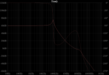
Cordell HEC Return Ratio
OK. here is the Return Ratio (A.K.A Loop Gain), at the OPS of the Cordell HEC amplifier.
At least, it's a macro-model-front-end version from JCX, that I have modified to use semiconductor models from Cordell_Models.
I made the modification because the JAES article did not have details of semiconductor types so I chose convenient ones.
I can't be sure the result is completely accurate but I think it shows the correct type of behaviour.
The low frequency peak has a scary look but is harmless, just like the similar peak in TPC.
In fact the entire plot looks very similar to TPC, and HEC can be considered as a TPC scheme from the perspective of the OPS.
The OPS is the dominant source of distortion in a well done class B+ amplifier so HEC is then, essentially, another TPC scheme.
Note that the peak means the Return Ratio starts to climb from 20 kHz.
This extra feedback is perfectly placed to hammer the distorted harmonics of a 20 kHz signal. No wonder this amp did well in 20 kHz THD tests.😉
Note also that the peak in the phase curve happens essentially perfectly at the ULGF, as one would want for stability.
There may be a little luck in there, I haven't simulated the front end details and the models are only reasonable guesses, but I assume Bob tweaked the amp based on real world tests.
Best wishes
David
Attachments
Last edited:
I just find the principles of feedback very interesting and in the practical sense, trying to deal with the LG of my pet project =) I admire mcduk99's project; he already got a working prototype goingI am indeed, I hope my comments can help improve projects, not depress people😉
And we can't stop just when M. Box has commented favourably, we have to earn 5 stars in case he rates the thread.
I will post simulation results of Bob's amp, based on JCX's ASC.
Best wishes
David
 . Finally giving HEC a real try and see its impressive results I wanted to seriously consider including it in the final schematic of my amp, so I began playing with it. It's interesting to see my bode plots are similar, and looking at Bob's MF amp's plot, I can see that with output inductor it would be stable. I assume it simulates as stable on various test patterns too (I like Bigun's sine-with-square-wave-notches-imposed test pattern as it's very revealing, especially if you extend the pattern to impose different frequency squares, making the sine/square ratio variable as well).
Funny to see that both Bob's and other's plots show this 'step-up' in gain just after the gain passed below unity. You can get to smooth that out by adding capacitance from the collectors of the driver transistors (that drive the mosfets) to their bases. It comes at the cost of phase margin; the phase peak lowers a bit likewise.
Still, I somehow do not trust my loop gain plots because of contrary results between plots and simulations.
Last edited:
...I can see that with output inductor it would be stable...
It does not need an output inductor to be stable, it already is stable.
Of course, an output inductor will help it stay stable with a capacitive load.
Funny to see that both Bob's and other's plots show this 'step-up' in gain just after the gain passed below unity.
This is not a coincidence, it's called a Bode Step and helps the stability of the amp.
You can get to smooth that out ...
No! We are suspicious of bumps in the input-to-output response of the amplifier, often called the closed loop response.
That name can confuse because people assume we want the response of the loop itself to be smooth.
But the optimum "loop gain", better called Return Ratio, is not a simple line!
Bode showed this in his book back in 1940 (I don't want to be repetitious but I really recommend it).
This is similar to my comment to Paul that his concern about the peak is also mostly unwarranted.
It comes at the cost of phase margin; the phase peak lowers a bit likewise.
Exactly. We put the step in precisely to raise the phase peak and improve the PM.
Still, I somehow do not trust my loop gain plots because of contrary results between plots and simulations.
Perhaps you have not checked at the correct points. Even Dr Middlebrook says this is an easy mistake to make, and even some of the experts in DIYAudio have done it.
Post the contrary results and we can check them and try to understand better.
Best wishes
David
Last edited:
Yeah I specifically meant with a capacitive load. The plot indeed looks like a TPC compensated network and found an input inductor to be necessary to deal with pure capacitive loads.It does not need an output inductor to be stable, it already is stable.
Of course, an output inductor will help it stay stable with a capacitive load.
Yeah I have been using this as a tuning mechanism to trade between PM/GM. However, if those caps I spoke of are too low, those bumps below UG may peak back above UG. Is that not disturbing? In spectra plots this comes back as a lot of harmonics 'activity' around the ULGFThis is not a coincidence, it's called a Bode Step and helps the stability of the amp.
No! We are suspicious of bumps in the input-to-output response of the amplifier, often called the closed loop response.
That name can confuse because people assume we want the response of the loop itself to be smooth.
But the optimum "loop gain", better called Return Ratio, is not a simple line!
Bode showed this in his book back in 1940 (I don't want to be repetitious but I really recommend it).
This is similar to my comment to Paul that his concern about the peak is also mostly unwarranted.
Exactly. We put the step in precisely to raise the phase peak and improve the PM.
This might be well possible. I'm still using the Tian probe in the global feedback loop as demonstrated by LTspice's demo file, but maybe with the HEC I have to relocate the probe.Perhaps you have not checked at the correct points. Even Dr Middlebrook says this is an easy mistake to make, and even some of the experts in DIYAudio have done it.
Post the contrary results and we can check them and try to understand better.
Best wishes
David
I'll take your advice and see if I can work myself through Bode's book. I fear it will only give more questions lol.
P.S. I fear posting my full schematic as it is a bit different from the mold and my point is getting it to work and build a working prototype, both to create a wire with gain and for the technical challenge / achievement, much like mcduk99 is doing 🙂 I want to prove my VAS topology does work in real (bread-board prototype already does), but also want this to be the best amp I could possibly achieve myself. Here, 'best' means as in specs performance. As long as it fulfills the "wire-with-gain", then I'll be satisfied sound wise.
- Status
- Not open for further replies.
- Home
- Amplifiers
- Solid State
- Middlebrook "GFT" probe?