This is not a coincidence, it's called a Bode Step and helps the stability of the amp.
Best wishes
David
Hi David,
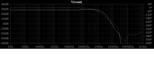
What do you think about this Loop Gain, it is from the CFA, asc file attached, Bode Step to pronounced?
BR Damir
Attachments

What do you think about this Loop Gain... Bode Step to pronounced?
Hi Damir
When any kink in the loop gain is -10 dB or more down then it is not really a problem.
The check is the amplifier response, there is a little bump but it is well below 0 dB so no cause for concern.
But as a rule of thumb, I try not to have the loop gain plot actually peak after the ULGF, I just want it to flatten but not climb back up.
I don't have a mathematical justification for this, at the moment, it just seems reasonable to me.
So I would flatten that Bode Step just a little.
Technically, the best measure is probably not PM and GM, which checks only two points, but the closest approach of the loop gain curve to the critical (unstable) point.
You can look at this on a Nyquist plot but it's not very convenient.
Some kind of Nyquist-type plot but with amplitude in dB would be easier.
I haven't seen this but I can't be the first to think of it, I will look more, any information appreciated.
Best wishes
David
Attachments
Last edited:
Hi Damir
When any kink in the loop gain is -10 dB or more down then it is not really a problem.
The check is the amplifier response, there is a little bump but it is well below 0 dB so no cause for concern.
But as a rule of thumb, I try not to have the loop gain plot actually peak after the ULGF, I just want it to flatten but not climb back up.
I don't have a mathematical justification for this, at the moment, it just seems reasonable to me.
So I would flatten that Bode Step just a little.
Technically, the best measure is probably not PM and GM, which checks only two points, but the closest approach of the loop gain curve to the critical (unstable) point.
You can look at this on a Nyquist plot but it's not very convenient.
Some kind of Nyquist-type plot but with amplitude in dB would be easier.
I haven't seen this but I can't be the first to think of it, I will look more, any information appreciated.
Best wishes
David
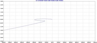
David, this is Nyquist plot around point zero, it looks strange but do not encompass it !
BR damir
Attachments
I didn't mean to scare you, what you have is pretty solid.
That spike looks bad but is actually not a cause for concern.
In fact, there are even some potential benefits there.
Hi David,
It's not just the peak but the phase change associated with the rising edge.
I am indeed, I hope my comments can help improve projects, not depress people😉
And we can't stop just when M. Box has commented favourably, we have to earn 5 stars in case he rates the thread.
Yes, must earn 5 stars. 😉
Your comments have helped massively. Loop analysis is IMHO essential when designing amplifiers. It's no good if the amp is prone to any sort of oscillation / instability. It's better to be aware of these issues than be ignorant of them. 🙂
Good to know that the HEC version of my project is still viable. Just need to work out which direction to take it in now. MIC is playing on my mind...
No! We are suspicious of bumps in the input-to-output response of the amplifier, often called the closed loop response.
That name can confuse because people assume we want the response of the loop itself to be smooth.
But the optimum "loop gain", better called Return Ratio, is not a simple line!
Bode showed this in his book back in 1940 (I don't want to be repetitious but I really recommend it).
This is similar to my comment to Paul that his concern about the peak is also mostly unwarranted.
This goes against my instincts. See peaks in plots as warning signs. But this is probably wrong. What are the warning signs in open loop responses apart from meeting the conditions for oscillation?
EDIT: I see you have already answered this for Damir...
Exactly. We put the step in precisely to raise the phase peak and improve the PM.
Have noticed something like this while simulating the 3EF version of my amp. Could not match the performance of the HEC version while keeping the same stability margins. Is it reasonable to consider a feed forward path as the opposite of a feed back path? In that it cancels some of the "phase lag" within feedback loops that contain a feed forward path?
Paul
David, this is Nyquist plot around point zero
I think it is best to set the real and complex parts to the same scale.
Then you can easily see the closest point of approach because it's just a circle centred on (-1, 0i), and I have drawn it in white.
Note that it is not at 180, which would be a level line.
Best wishes
David
Attachments

I'll take your advice and see if I can work myself through Bode's book. I fear it will only give more questions lol.
Hi MagicBox,
The book is very in-depth and is big undertaking to read. Prepare to invest a lot of time. Personally, I'm finding answers and questions.
P.S. I fear posting my full schematic as it is a bit different from the mold and my point is getting it to work and build a working prototype, both to create a wire with gain and for the technical challenge / achievement, much like mcduk99 is doing 🙂 I want to prove my VAS topology does work in real (bread-board prototype already does), but also want this to be the best amp I could possibly achieve myself. Here, 'best' means as in specs performance. As long as it fulfills the "wire-with-gain", then I'll be satisfied sound wise.
Don't fear posting your schematic. Would be interesting to see and would be good to see some loop analysis from it. 🙂
Sounds like we have similar goals. I build strip board prototypes these days as I once designed an amp and went straight to PCB. It didn't work and ended up a big waste of money. Also, it is good to simulate some thing then make the changes and see what happens in real life.
Paul
It's not just the peak but the phase change associated with the rising edge.
That is an example of Non-Minimum Phase, phase normally climbs as the amplitude peaks, here it falls.
NMP is very rarely desirable, but here, at the frequency band near the peak, the amp is so far from oscillation that it doesn't matter.
I have had a "robust discussion" with Walter (Waly) about NMP http://www.diyaudio.com/forums/solid-state/260452-non-minimum-phase.html.
My attempts to make my case irrefutable may not have convinced Walter but they forced me to really look carefully. Very educational.
I think MIC has several benefits but have never considered the interaction of MIC and HEC.MIC is playing on my mind...
...Is it reasonable to consider a feed forward path as the opposite of a feed back path? In that it cancels some of the "phase lag" within feedback loops that contain a feed forward path?
Unfortunately feed-forward doesn't help, you can't cancel added phase from Non-Minimum Phase behaviour. Would require a time machine to "look ahead". (Actually possible in some applications where there is feedback, but over space, as in optics, rather than time. Really can look ahead.)
Best wishes
David
Last edited:
That is an example of Non-Minimum Phase, phase normally climbs as the amplitude peaks, here it falls.
NMP is very rarely desirable, but here, at the frequency band near the peak, the amp is so far from oscillation that it doesn't matter.
I have had a "robust discussion" with Walter (Waly) about NMP http://www.diyaudio.com/forums/solid-state/260452-non-minimum-phase.html.
My attempts to make my case irrefutable may not have convinced Walter but they forced me to really look carefully. Very educational.
Will have a read... Thank you.
I think MIC has several benefits but have never considered the interaction of MIC and HEC.
With the knowledge gained so far, for some reason, I feel able to analyse this... 😕
Maybe TP-MIC could be used. I think Dadod has played with this idea before?
Unfortunately feed-forward doesn't help, you can't cancel added phase from Non-Minimum Phase behaviour. Would require a time machine to "look ahead". (Actually possible in some applications where there is feedback, but over space, as in optics, rather than time. Really can look ahead.)
Best wishes
David
But could you cancel minimum phase behaviour? If you know the transfer function of a loop can you add some feed forward to improve things? Just trying to get my head round how HEC can provide better performance and stability at the same time. Is it the feed forward path bringing the benefits?
Paul
I think it is best to set the real and complex parts to the same scale.
Then you can easily see the closest point of approach because it's just a circle centred on (-1, 0i), and I have drawn it in white.
Note that it is not at 180, which would be a level line.
Best wishes
David
I studied that think a looong time ago at University, and something left, but more I forgot.
What means if that line is not in level?
BR Damir
Maybe TP-MIC could be used. I think Dadod has played with this idea before?
Paul
Paul, I used TP-OIC in my CFA, somehow could not get good result with MIC.
Damir
Will have a read... Thank you.
I meant it was very educational to me! I didn't mean to claim that anyone else would find it so.
Maybe TP-MIC could be used. I think Dadod has played with this idea before?
My preferred circuit is a TwoPole version of MIC.
There are both practical benefits and some theoretical ones.
That is in a complementary LTP implementation.
But could you cancel minimum phase behaviour? If you know the transfer function of a loop can you add some feed forward to improve things? Just trying to get my head round how HEC can provide better performance and stability at the same time. Is it the feed forward path bringing the benefits?
You can cancel phase from MP behaviour.
Feed forward for a known transfer function is not usually practical in an audio amplifier. Distortion can be reduced to PPM anyway.
I don't think HEC has any special properties, still subject to the same rules about trade-off between loop speed, stability and distortion reduction.
Perhaps your EF is just not quite optimized yet.
But I still need to think more about feed forward.
Best wishes
David
Last edited:
What means if that line is not in level?
Only that the worst case is not at 180.
So the GM, which is at 180, doesn't tell the full story.
In your case it's very close, so the GM tells more about stability than the PM.
Best wishes
David
I meant it was very educational to me! I didn't mean to claim that anyone else would find it so.
It may give a little insight into NMP though. 😉
You can cancel MP behaviour. But not usually practical in an audio amplifier.
Distortion can be reduced to PPM anyway.
I don't think HEC has any special properties, still subject to the same rules about trade-off between loop speed, stability and distortion reduction.
Perhaps your EF is just not quite optimized yet.
But I still need to think more about feed forward.
Best wishes
David
So theoretically possible to cancel phase... But not something you need / want to do within an audio amplifier.
Good to know that the same rules apply to the HEC. Always thought you had a fixed amount of stability for a given circuit and you could trade that for performance. Amplifier design appears to be full of triangular relationships. the 3EF wasn't pursued for long. It was more to see how the HEC affected other loops.
Is it a reasonable assumption that TP-MIC can equal the performance DTMC with the same stability? With both schemes optimised.
Paul
Analyzing multi loop systems, that's a tough topic...
To the extend that I am aware of, there are a few methods, which I would put in two categories: one is a simplified, providing "sufficient" stability conditions, the other one is general, but unfortunately difficult to implement.
Under the first category fall the two methods, already quoted here, described by Hurst in IEEE TRANSACTIONS ON CIRCUITS AND SYSTEMS-11: ANALOG AND DIGITAL SIGNAL PROCESSING, VOL. 42, NO. 12, DECEMBER 1995
a) If the feedback loops have a break point in common, then by breaking the loops at that point the stability analysis is performed as if it were a single loop case.
b) A multi-loop feedback which comprises one global feedback network and several inner feedback loops can be analyzed by just breaking the global feedback network, if each of its inner feedback loops is stable by itself. The inner loops do not need to be opened during this stability analysis.
Please note that these two methods are providing only sufficient stability criteria, meaning that there are stable systems that will be revelead as unstable by these methods. b) above has an interesting implication for audio: the usual Bode stability criteria for the global loop make sense only if the Miller loop, or any common mode loops, etc... are stable. Another typical example that I am sure many DIYers encountered is an output stage (triple, CFP) instability which is not shown in the global loop stability analysis but which can be a blue smoke generator, nonetheless. Otherwise said, if any of these inner loops are not stable, the global stability is questionable, even if we are shown healthy phase and gain margins.
In the second category we have the general methods. The safest way is to brute force calculate the Eigen values of the closed loop circuit matrix, a la Cherry. Unfortunately, in practice, even if there are software packages performing such a daunting task, numerical errors can be very large, if the poles are widely separated and/or the system order is (as usual) rather large. There are of course solutions, but they are all far beyond the reach of the DIY community.
The other method (I think I quoted this before) is called sequential loop closure (SLC). It involves the following steps:
a. Open all feedback loops so that the system is stable.
b. Determine and analyze the loop gain of one feedback loop with all other loops open. Count the number of encirclements of the Nyquist point. The first number of encirclements will always be positive (clockwise).
c. Close that loop and determine and analyze the loop gain of the next loop. Now the number can be positive (clockwise) or negative (counter clockwise). Keep track of the net number of encirclements of the Nyquist point.
d. Close that loop and do the same analysis for the next loop, etc...
e. At the end, if the net number of encirclements (clockwise minus counter clockwise) equals zero, the system is stable. If the net number of encirclements is greater than zero, the system is unstable (you will of course note that this number can't be negative).
The SLC method can be used with Spice, however it is barely useful. In audio, where we usually do not want to deal with pathological cases (though important in some control systems) when two unstable inner loops may lead to a globally stable system. Therefore, I believe that Hurst criteria are covering everything we need for analyzing audio circuits. Everything else if fluff clouding the picture.
Last edited:
So theoretically possible to cancel phase... But not something you need / want to do within an audio amplifier.
I re-worded that after I posted because I realized it was not very clear.
In a sense we cancel phase all the time, every time we equalize a signal, the phase is altered.
If the frequency response was made unequal by an MP system then if we equalize it back to flat with an MP system then the phase will be restored too.
To try to cancel a known non-linearity is a somewhat different concept.
Is it a reasonable assumption that TP-MIC can equal the performance DTMC with the same stability? With both schemes optimised.
On my MIC development circuit, I have had better results with TPC, so far.
This surprises me a bit, I expected TMC to be a little superior.
I still don't have a clear explanation for my results.
I swapped a few emails with Edmond and finally sent him a copy of the circuit to see if he could do better but so far he hasn't come back.
The difference is not dramatic, just that TPC was a little simpler for comparable performance.
This is may be partly a function of my particular circuitry, low impedance and with a simple EF2 OPS.
I am sufficiently satisfied with the results that I have not checked into DTMC except for a few back-of-envelope drafts.
Best wishes
David
Last edited:
I re-worded that after I posted because I realized it was not very clear.
In a sense we cancel phase all the time, every time we equalize a signal, the phase is altered.
If the frequency response was made unequal by an MP system then if we equalize it back to flat with an MP system then the phase will be restored too.
To try to cancel a known non-linearity is a somewhat different concept.
On my MIC development circuit, I have had better results with TPC, so far.
This surprises me a bit, I expected TMC to be a little superior.
I still don't have a clear explanation for my results.
I swapped a few emails with Edmond and finally sent him a copy of the circuit to see if he could do better but so far he hasn't come back.
The difference is not dramatic, just that TPC was a little simpler for comparable performance.
This is may be partly a function of my particular circuitry, low impedance and with a simple EF2 OPS.
I am sufficiently satisfied with the results that I have not checked into DTMC except for a few back-of-envelope drafts.
Best wishes
David
David, have you tried combining TPC and Cherry? Both a 2nd order miller compensation from VAS out to in, and then either 1st or 2nd order Cherry feedback, from OUT to VAS in. This is a 'discrete' "TMC", which is better tunable. I'm using this in my schematic with good results given the massive OLG the schematic has.
my earlier Lurie Classical Control renewed website ref Classical Feedback Control
has his book 's frequency response shaping/compensation chapter showing Bode's "Optimum" roll-off, Bode Step and the "Bode Step Toolbox" appendix as free samples
has his book 's frequency response shaping/compensation chapter showing Bode's "Optimum" roll-off, Bode Step and the "Bode Step Toolbox" appendix as free samples
Is it a reasonable assumption that TP-MIC can equal the performance DTMC with the same stability? With both schemes optimised.
This almost certainly varies from topology to topology and also the exact devices used.On my MIC development circuit, I have had better results with TPC, so far.
This surprises me a bit, I expected TMC to be a little superior.
I still don't have a clear explanation for my results.
I swapped a few emails with Edmond and finally sent him a copy of the circuit to see if he could do better but so far he hasn't come back.
The difference is not dramatic, just that TPC was a little simpler for comparable performance.
This is may be partly a function of my particular circuitry, low impedance and with a simple EF2 OPS.
I've had good 'real life' results in da last Millenium from Two Pole Cherry .. ie better than plain TPC.
Today, I prefer Pure Cherry cos less bits and the ease which you can have zillion dB PSSR by adding a single CGO/NPO cap.
In this Millenium, I'm just playing with LTspice ... and it is obvious that different topologies have different 'optimum' compensation strategies.
And you define your 'optimum' ... THD, stability, overload, recovery bla bla
Vas is DTMC?I am sufficiently satisfied with the results that I have not checked into DTMC except for a few back-of-envelope drafts.
This almost certainly varies...
Yes, hence my comment. But what I want is a rule about when to favour one or the other.
Just to try them all and pick the best isn't very sharp.
Have you any ideas about this?
I've had good 'real life' results in da last Millenium from Two Pole Cherry .. ie better than plain TPC.
I don't see why, for comparable stability when properly measured - that is, with the probe in the correct place for that feedback loop structure.
I suppose there are small differences in the shunt loads but I expect that to be very minor.
It's not a simple question, and our previous discussions still haven't properly sorted it out, I look forward to more. 😉
Do you have an example ASC where TP Cherry beats equivalent plain TPC?
Vas is DTMC?
I think Paul means Double Transitional Miller Compensation, another of Edmond Stuart's acronyms.
Appropriately to your query, around the "VAS".
Best wishes
David
Last edited:
- Status
- Not open for further replies.
- Home
- Amplifiers
- Solid State
- Middlebrook "GFT" probe?