This sound character refer to the high level section (both for inverted and non inverted ones).Only two to go....
Now serious.
Jeff Rowland is together with Nelson Pass in my opinion one of the nicest guys within the world of the high-end audio.
I'm communicating with him (and Nelson) for over 25 years now regarding their products and they always helped me out.
I've had expensive pre-amps from Levinson, Krell, Threshold and Audio-Research and the C1 in its different incarnations is to me the most musical sounding of them all.
You can see that he's still updating his first commercially available pre-amp (1986). Remember all the modular Levinsons? They were never updated although MLAS & Madrigal used the modular construction as a selling point against obsolence.
These new line level modules are only $ 300.00 the four so not $ 400,00 a piece as I saw mentioned somewhere in this thread.
Do not know the exact price of the High Level Phono modules but they're probably somewhat more expensive then the line level ones.
Jeff sended me the latter for a wrong level potted phono module and charged only that one, great!
PSU still runs pretty hot but less the with the potted modules.
Sound is still mellow but there's more background detail, more air, crispness, instrument's are more defined and separate, sound has more extension and depth.
Hope you all enjoy you C1's and maybe you will get the updates that are OPEN so you can see what's on them instead of using X-Rays or 500 degrees Heat canons,
Cheers Robert
Thank you very much for this description.
Are there any experiences concerning similar differences by listening tests via RIAA MC input between the old and new modules ?
And a second question: From what serial number were the new modules at all places in use?
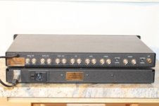
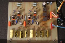
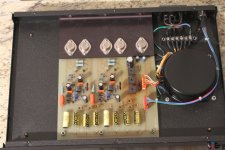
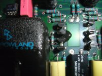
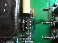
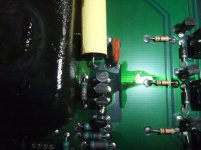
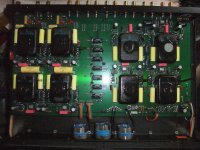
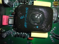
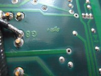
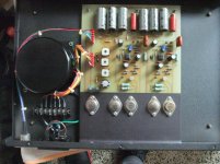
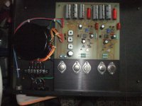
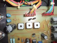
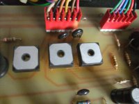
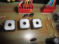
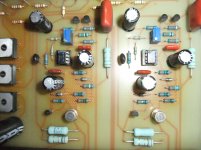
BTW - below jpg attachements from a newer version in mixed mode (old modules in potted version for RIAA section and new not potted version for line level section - found on a japanese/far east page and this offer:
http://www.usaudiomart.com/details/...oherence-one-series-ii-preamp-w-lomc-modules/)
On the last both images are clearly to see the PCB areas, where the good known thermal issues on PCB is present, mainly near by the connector of main transformer (right hand of the rectifier trio).
An appropriate maintenance is absolutely necessary before operating again. Otherwise a total damage isn't rule out.
Attachments
-
 1323637-jeff-rowland-design-group-coherence-one-series-ii-preamp-w-lomc-modules.jpg213.6 KB · Views: 1,232
 -
 1323638-jeff-rowland-design-group-coherence-one-series-ii-preamp-w-lomc-modules.jpg495.1 KB · Views: 1,135
 -
 1323639-jeff-rowland-design-group-coherence-one-series-ii-preamp-w-lomc-modules.jpg191.5 KB · Views: 1,132
 -
 1326694-jeff-rowland-design-group-coherence-one-series-ii-preamp-w-lomc-modules.jpg410.4 KB · Views: 1,149
 -
 649299399_thumb_5b2a2b376991d2beee42ef7c1d9af03f.jpg18 KB · Views: 1,107
 -
 1326695-jeff-rowland-design-group-coherence-one-series-ii-preamp-w-lomc-modules.jpg278.4 KB · Views: 491
 -
 1326696-jeff-rowland-design-group-coherence-one-series-ii-preamp-w-lomc-modules.jpg318.7 KB · Views: 527
Last edited:
a friend of me, which have a Coherence One still in use, is looking for a second device of this model in not operation condition (for spare parts and thus facilitated service) for reasonable costs.
Please let me know, if someone has one.
My email address:
kirschner-hifiQweb_de
(please replace "Q" and "_" by the correct characters).
Thank you very much.
Please let me know, if someone has one.
My email address:
kirschner-hifiQweb_de
(please replace "Q" and "_" by the correct characters).
Thank you very much.
DC coupled output without reliable DC-protection
From a user I have again the model "Coherence ONE" (Series II) on my desk, which have destroy the bass driver of the Klipsch Heresy. The reason therefore is the fact, that the right channel of the inverted line module provide temporary DC voltage of approximately 15-16 volts and the absence of the music signal (this happens not often and mostly while high ambient temperature).
Without occured DC at this output the preamp works perfect without any unwanted effects.
By interchanging of the pluggable inverting line amp modul (series II) from one channel to the other I note while occuring of this error the DC on the left channel. This means, the inverting line amp modul itself (and not possibility errors on the main board) is the reason for this unwanted DC.
The user had connect the power amp for the sattelite speakers (Klipsch Heresy) at the inverted outputs and the subwoofer plate-amp at the non inverted outputs.
In this matter I note additional this:
- if I press the phase switch (inverting and non-inverting signals interchanges the assignments at the cinch-sockets) no signal at all outputs is present (DC protect is active).
- if I press the phase switch again (also default position after switch-on the main switch), music signal is present at all outputs except from that one with DC voltage, if this error occured.
This means for me, that the DC protection works only either on the non inverted outputs (phase reverse switch not active as mostly usual) or on the inverted outputs (phase reverse switch active - now non inverted outputs without DC protect).
The question is now, how I modify the DC-protector in such kind, that I have effectice DC protection at all channels.
Schematic is here (post #53 first PDF file):
http://www.diyaudio.com/forums/soli...d-coherence-1-schematic-modules-wanted-6.html
Please note: in the pdf-file of post #54 (schematic of the actually preamp) there is follow misprint from me:
The 357K resistor from the inverted output to PIN2, µPC812C isn't in use (only right channel is show). Otherwise the above mentioned issue wasn't present.
At first glance the most easy solution is adding this both 357K resistors, which I mistakenly drawn in my own created schematic diagram.
But I have headache, because in cases, where occurs DC with different polarity on two modules, the DC protector also don't work in the right way (and switch the output to GND).
Maybe there is a more elegant solution resp. possibility of extension for a real reliable DC protection of all 4 channels.
Thank you very much for advices.
any news?
From a user I have again the model "Coherence ONE" (Series II) on my desk, which have destroy the bass driver of the Klipsch Heresy. The reason therefore is the fact, that the right channel of the inverted line module provide temporary DC voltage of approximately 15-16 volts and the absence of the music signal (this happens not often and mostly while high ambient temperature).
Without occured DC at this output the preamp works perfect without any unwanted effects.
By interchanging of the pluggable inverting line amp modul (series II) from one channel to the other I note while occuring of this error the DC on the left channel. This means, the inverting line amp modul itself (and not possibility errors on the main board) is the reason for this unwanted DC.
The user had connect the power amp for the sattelite speakers (Klipsch Heresy) at the inverted outputs and the subwoofer plate-amp at the non inverted outputs.
In this matter I note additional this:
- if I press the phase switch (inverting and non-inverting signals interchanges the assignments at the cinch-sockets) no signal at all outputs is present (DC protect is active).
- if I press the phase switch again (also default position after switch-on the main switch), music signal is present at all outputs except from that one with DC voltage, if this error occured.
This means for me, that the DC protection works only either on the non inverted outputs (phase reverse switch not active as mostly usual) or on the inverted outputs (phase reverse switch active - now non inverted outputs without DC protect).
The question is now, how I modify the DC-protector in such kind, that I have effectice DC protection at all channels.
Schematic is here (post #53 first PDF file):
http://www.diyaudio.com/forums/soli...d-coherence-1-schematic-modules-wanted-6.html
Please note: in the pdf-file of post #54 (schematic of the actually preamp) there is follow misprint from me:
The 357K resistor from the inverted output to PIN2, µPC812C isn't in use (only right channel is show). Otherwise the above mentioned issue wasn't present.
At first glance the most easy solution is adding this both 357K resistors, which I mistakenly drawn in my own created schematic diagram.
But I have headache, because in cases, where occurs DC with different polarity on two modules, the DC protector also don't work in the right way (and switch the output to GND).
Maybe there is a more elegant solution resp. possibility of extension for a real reliable DC protection of all 4 channels.
Thank you very much for advices.
a friend of me, which have a Coherence One still in use, is looking for a second device of this model in not operation condition (for spare parts and thus facilitated service) for reasonable costs.
Please let me know, if someone has one.
My email address:
kirschner-hifiQweb_de
(please replace "Q" and "_" by the correct characters).
Thank you very much.
any news?
Line:
U1: (small transistor) LM78L, Positive Voltage regulator
U2: (small transistor) MC79L, Negative Voltage regulator
U3: (8 PIN IC): Analog Device, AD746N
C1 & C3: 16V 100 uF (electrolytic caps)
C2 & C4 (blue): 104 (0,1 uf)
C5 & C6 (brown): 100 (10 pF)
Phono is the same except for additional:
ERO CAP: MKC1862 1uF
At your service... ;-)
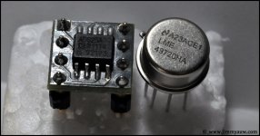
The AD825 could be a better choise - go to
AD825 and LM49720 – Jimmy's Junkyard
Greetings Robert
The AD825 and LME49720 could be also an optionLine:
U1: (small transistor) LM78L, Positive Voltage regulator
U2: (small transistor) MC79L, Negative Voltage regulator
U3: (8 PIN IC): Analog Device, AD746N
C1 & C3: 16V 100 uF (electrolytic caps)
C2 & C4 (blue): 104 (0,1 uf)
C5 & C6 (brown): 100 (10 pF)
Phono is the same except for additional:
ERO CAP: MKC1862 1uF
At your service... ;-)
Greetings Robert
AD825 and LM49720 – Jimmy's Junkyard
Attachments
Last edited:
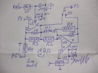
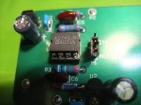
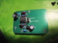
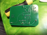
For replacing defective inverted line modules I have now got the new versions for replacement, equipped with dual Op-Amp AD746JN - go to the attached images. First image is the schematic diagram. Next year I will compare the non inverted old ones with the new versions in the non inverted mode by a listening test.Only two to go....
Now serious.
Jeff Rowland is together with Nelson Pass in my opinion one of the nicest guys within the world of the high-end audio.
I'm communicating with him (and Nelson) for over 25 years now regarding their products and they always helped me out.
I've had expensive pre-amps from Levinson, Krell, Threshold and Audio-Research and the C1 in its different incarnations is to me the most musical sounding of them all.
You can see that he's still updating his first commercially available pre-amp (1986). Remember all the modular Levinsons? They were never updated although MLAS & Madrigal used the modular construction as a selling point against obsolence.
These new line level modules are only $ 300.00 the four so not $ 400,00 a piece as I saw mentioned somewhere in this thread.
Do not know the exact price of the High Level Phono modules but they're probably somewhat more expensive then the line level ones.
Jeff sended me the latter for a wrong level potted phono module and charged only that one, great!
PSU still runs pretty hot but less the with the potted modules.
Sound is still mellow but there's more background detail, more air, crispness, instrument's are more defined and separate, sound has more extension and depth.
Hope you all enjoy you C1's and maybe you will get the updates that are OPEN so you can see what's on them instead of using X-Rays or 500 degrees Heat canons,
Cheers Robert
Are even such modules available as replacement for the phono MC input stage modules ?
P.S.: the URL in my previous post is death. check out this URL:
AD825 and LM49720 – Jimmy's Junkyard
Attachments
Last edited:
For replacing defective inverted line modules I have now got the new versions for replacement, equipped with dual Op-Amp AD746JN - go to the attached images. First image is the schematic diagram. Next year I will compare the non inverted old ones with the new versions in the non inverted mode by a listening test.
Are even such modules available as replacement for the phono MC input stage modules ?
P.S.: the URL in my previous post is death. check out this URL:
AD825 and LM49720 – Jimmy's Junkyard
This is my first posting to DiyAudio. Like many designers, i do not post to forums of any type. Many designers quit posting after being belittled numerous times from those that consider themselves experts. Sitting on a bench and throwing together an excellent performing and sounding circuit is no where near the challenge of actually manufacturing that circuit, marketing, selling and servicing that product decades later from its inception. So be considerate and understanding of those that have actually started and successfully run an audio manufacturing business for not only years, but decades. And don't think that many of us, if any at all, "get rich" on our business. If I had these aspirations, I would have continued working for Ampex Corporation after 1974. A small audio business is a great way to spend a lot of time and energy to make a little money for himself and employees, if he has any.
The Coherence One (C1) was my first preamplifier designed for the audiophile market.
I designed everything from the circuit boards which I laid out by hand with tape, pads and mylar with an exacto knife on a light table, to the chassis design and other mechanical components. Same with the schematics, as this was before widespread use of computers and .pdf files. The original hand drawn schematics are still in my flat files, along with all of the other drawing and designs done in like manner throughout the '90s. If someone wants an original schematic of the preamp or the potted modules I will gladly make copies and provide them. Rich Maez worked for me some years ago in sales and did attempt to copy and digitize some schematics so they could be emailed, but Rich was not a technician, and therefore there were many errors which were not proofed by me. If nobody has these schematics and wants to "melt the epoxy", it would be much easier just to ask me via the website and I would provide them.
We encapsulated all of the early modules, both amp and preamp critical circuitry, with thermally conductive epoxy, not to hide the circuitry but provide circuit stability by equalizing thermal gradients and mainly to modularize the critical circuitry for ease of service down the road. Potting modules is a royal pain in the ***, the weighing of the two-part epoxy, dispensing of the time critical and messy epoxy, and high cost of thermally conductive epoxy. I have nothing to hide and if someone wants to copy my design, then go right ahead. The chances of "a circuit" going mainstream and becoming a success in the marketplace are slim. That is my competitive advantage, by actually being the first to sell the product and by the time it was copied, I would have probably moved on to an improved version. However, the downside to encapsulation is the possible "compression' of certain components during the curing process which can lead to failure in the long term and the slight but undesirable dielectric and dissipation effects from the epoxy material itself. In later years we would just partially pot the modules with just enough epoxy to hold the circuitry within the module can for support but minimize the dielectric effect.
A manufacturer must resort to module or subassembly field repair instead of component level troubleshooting and repair to be successful in the long term. Finding technicians with good circuit knowledge and soldering skills was very difficult 20 or 30 years ago and has become generally impossible within the last 10 years. I have prided myself by producing products that endure the test of time simply by making them repairable by those with a very little technical knowledge; simply pull the module out and replace with a new one. No need to send a bulky and heavy chassis across the country for repair.
The current replacement for line C1 amp modules (only Series II) is a simple FET input op amp circuit for gain and phase inversion, the AD746. This is a very good ultralow noise high speed BiFETOp Amp, even by todays standards. These can just be plugged in to the motherboard by the average audiophile and an on board jumper can be placed to make the module inverting or non-inverting
All of the encapsulated modules, both phono and line, were a simple circuit which I thought that I had invented on my own, but much later found out by perusing a National data book that the basic circuit was used in one of their high speed IC's later on. It is JFET input, Toshiba 2SK170, cascoded and sourced with a current mirror towards the positive supply, then cascoded again towards the negative supply via a cascoded current mirror off the negative rail. Gain was set by the ratio of first FET source resistor and the cascade/cascode load resistor. The signal was then buffered by a LM6321N buffer and DC servoed by an AD712 integrator. The higher voltage Series 1 modules had the servo external to the module, the Series 2 integrator was located local to the module circuit. The Phono modules used 4 paralleled 2SK147 FETs for the first stage for lowest noise and simply cascoded by 2SJ74's to the negative rail via a paralleled 2SK170 current source. This single gain stage was also buffered by an LM6321N. In the phono module case, the gain was set by the 75 microsecond pole provided by a resistor and capacitor going to ground to define the 2120 Hz. part of the RIAA curve, which is located outside of the module. We even used Vishay precision resistors for the gain setting on all modules for their low temp coefficient. If I get the time I will post these scribbled up schematics on this forum for those interested. Remember this was almost 35 years ago! We still have a large stock of original Toshiba FETs which I can sell to the DIY community.
We still have quite a bit of modules left in stock for service. The new line modules with the IC's do sound better according to users who have upgraded, and the classic original modules are still available. The original modules do have a nice pure sine wave 2X signal frequency harmonic component only, simply due to the lack of any negative feedback. The updated modules have no measurable distortion at all, 0.0001%, so it is up to the user what he wants.
There are some errors on the posted power supply schematic, so I can post the original also if I can get it copied down in size. Occasionally I see a few preamps with dried out capacitors, usually on the 12 volt relay supply. If a line module goes dc output, it will immediately short the outputs on all output phases, via the integrator and absolute value detector which is fed by each output phase. It is quick enough that I haven't heard of anyone's speakers being damaged but will possibly produce a loud pop.
To the best of my knowledge most, if not all of the Coherence One preamps are still loved and in use today. Many units have been updated from Series 1 to 2, which involved changing the modules and dropping the voltage on the power supply output from +/-49 volts to +/- 19 volts along with a few other modifications.
There were many versions of power supply transformers used. Not by design, but due to the usual supply chain difficulties from suppliers. Designing a custom transformer with multiple outputs and a very low radiated stray magnetic field was not easy 35 years ago, and is still probably a challenge even today. The best, not surprisingly, were of course from Japan, and these had a long lead time and were not cheap. Such are the rigors of manufacturing specialty audio.
I will try to keep track of this thread, but remember, this is a 30 to 35 year old product and I have long since moved on to other projects. I will continue to move into the future without being bogged down by the weight of the past so don't be surprised if you do not get a quick response to your inquiry. I still have a business to run, circuits to design and employees mortgages to pay.
And most of all, I am always learning something new everyday.
Jeff Rowland
This is my first posting to DiyAudio. Like many designers, i do not post to forums of any type. Many designers quit posting after being belittled numerous times from those that consider themselves experts...
Jeff, I'd wager that your design insights and experience would be interesting for most members here to read and benefit from in our DIY efforts. Don't be put off by the occasional belittling of a few. As you probably already know, a number of your industry peers frequently post here.
That said, I, for one, would be very interested in reading more of your reflections as an long time entrepreneur in the specialty audio industry. Not simply war stories, although those are fun to read too, but your assesment of key things you did right and did wrong as you look back over the years. If you could do it all over again, would you? That sort of stuff.
Thanks.
What a great post.
Remember many years ago when I had the Jeff Rowland Model 8 amp. Fantastic amp.
One of the incapsulated modules failed.
I sent an email to Jeff Rowland and the man himself answered.
They shippped 2 modules across the atlantic free of charge.
That is the best service I have encountered in my audio life") The Model 8 got to life again and has since then got a new happy owner. Thanks again.
The Model 8 got to life again and has since then got a new happy owner. Thanks again.
Remember many years ago when I had the Jeff Rowland Model 8 amp. Fantastic amp.
One of the incapsulated modules failed.
I sent an email to Jeff Rowland and the man himself answered.
They shippped 2 modules across the atlantic free of charge.
That is the best service I have encountered in my audio life
The Model 8 got to life again and has since then got a new happy owner. Thanks again.What is this ?
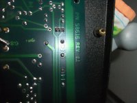
JRDG Coherence ONE - PCB: 58616 Rev.C.1 Serial-No: 00440 - what happened here ?
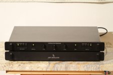
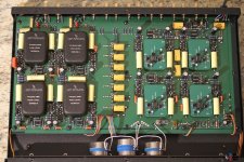
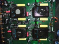
As can be seen in the attached images, there seem to be major problems here.
I guess, that the sealing tape pieces on top of the modules have liquefied - maybe by the age or maybe through heating.
I don't know the exact keyword in english for the here used kind of sealing tape:
Hannoband(R) BG1 Kompriband Fugendichtband Fugenband 10 / 2-4 mm - 10 Meter Rolle | Fenster-Hammer.de
I don't have the courage to switch-on this device for troubleshooting.
An idle test of the power supply itself (i. e. without the actually preamplifier) provides the following voltage values:
1) at the input of voltage regulator (behind the rectifiers): ± 72V6DC (based on 2x53V8AC)
2) at the output of voltage regulator: ∓49V3DC
That is about 2.5 times the values of the first device described here (go to the attached schematics in post #71).
Where should I start troubleshooting?
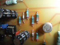
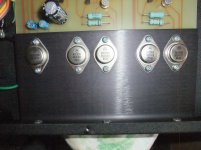
First and last image shows the PCB-version.
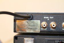
JRDG Coherence ONE - PCB: 58616 Rev.C.1 Serial-No: 00440 - what happened here ?
As can be seen in the attached images, there seem to be major problems here.
I guess, that the sealing tape pieces on top of the modules have liquefied - maybe by the age or maybe through heating.
I don't know the exact keyword in english for the here used kind of sealing tape:
Hannoband(R) BG1 Kompriband Fugendichtband Fugenband 10 / 2-4 mm - 10 Meter Rolle | Fenster-Hammer.de
I don't have the courage to switch-on this device for troubleshooting.
An idle test of the power supply itself (i. e. without the actually preamplifier) provides the following voltage values:
1) at the input of voltage regulator (behind the rectifiers): ± 72V6DC (based on 2x53V8AC)
2) at the output of voltage regulator: ∓49V3DC
That is about 2.5 times the values of the first device described here (go to the attached schematics in post #71).
Where should I start troubleshooting?
First and last image shows the PCB-version.
Attachments
-
 58616 Rev.C.1 SN 440 Main Board-I.jpg987.6 KB · Views: 540
 -
 58616 Rev.C.1 SN 440 Main Board-II.jpg981.4 KB · Views: 503
 -
 58616 Rev.C.1 SN 440 Main Board-III.jpg992.1 KB · Views: 499
 -
 58616 Rev.C.1 SN 440 Main Board-IV.jpg1 MB · Views: 495
 -
 58616 Rev.C.1 SN 440 Main Board-VI.jpg995.1 KB · Views: 492
 -
 58616 Rev.C.1 SN 440 Main Board-VII.jpg1,003.1 KB · Views: 190
 -
 58616 Rev.C.1 SN 440 Main Board-VIII.jpg989.4 KB · Views: 155
 -
 58616 Rev.C.1 SN 440 Main Board-IX.jpg1 MB · Views: 184
 -
 58616 Rev.C.1 SN 440 Main Board-X.jpg1,005.1 KB · Views: 273
 -
 58616 Rev.C.1 SN 440 Main Board-XII.jpg1,001.1 KB · Views: 217
Last edited:
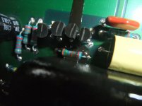
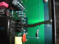
Images of Power Supply PCB Ser.-No 00440
A closer look reveals larger areas on the PCB of the discrete voltage regulators that have been exposed to permanent thermal stress.
Next time I will check the differences to my previous circuit diagram here posted.
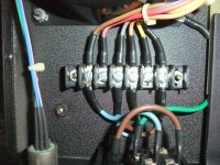
Surprisingly, the pin headers for connectors from the secundary windings of transformer do not show any overheating.
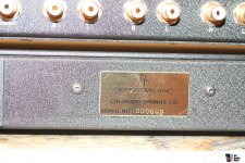
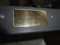
Last image shows the back plate with serial No.
A closer look reveals larger areas on the PCB of the discrete voltage regulators that have been exposed to permanent thermal stress.
Next time I will check the differences to my previous circuit diagram here posted.
Surprisingly, the pin headers for connectors from the secundary windings of transformer do not show any overheating.
Last image shows the back plate with serial No.
Attachments
-
 C1 PS SN 440 PCB-I.jpg1,011.9 KB · Views: 224
 -
 C1 PS SN 440 PCB-II.jpg1,018.6 KB · Views: 206
 -
 C1 PS SN 440 PCB-III.jpg1,014.2 KB · Views: 169
 -
 C1 PS SN 440 PCB-IV.jpg996.8 KB · Views: 137
 -
 C1 PS SN 440 PCB-V.jpg990.4 KB · Views: 143
 -
 C1 PS SN 440 PCB-VI.jpg1,005.3 KB · Views: 187
 -
 C1 PS SN 440 PCB-VII.jpg980.4 KB · Views: 153
 -
 C1 PS SN 440 PCB-VIII.jpg1,015.2 KB · Views: 154
 -
 C1 PS SN 440 Transf. prim-I.jpg1.1 MB · Views: 161
 -
 C1 SN 440-II.jpg1,005.5 KB · Views: 150
Last edited:
Last edited:
any news ?According the now presently informations there may be 7 different versions:
1) First revision without numbering (fact according presently schema) for +/-49VDC
2) Rev A S/N 001 to 125 (fact according presently second schema) for +/-51VDC
3) Rev A.1 S/N above 125
4) Rev B
5) Rev. B.1
6) Rev C
7) Rev C.1 (fact according exist PCB from preamp device with S/N 000614 for +/-20VDC)
Are my estimates concerning 2) to 6) correct ?
If yes, how many different potted devices are there at whole (please note: 4 different pieces for each revision !!!) ?
Are there replacement modules also for the showed high voltage version ?JRDG Coherence ONE - PCB: 58616 Rev.C.1 Serial-No: 00440 - what happened here ?
As can be seen in the attached images, there seem to be major problems here.
I guess, that the sealing tape pieces on top of the modules have liquefied - maybe by the age or maybe through heating.
I don't know the exact keyword in english for the here used kind of sealing tape:
Hannoband(R) BG1 Kompriband Fugendichtband Fugenband 10 / 2-4 mm - 10 Meter Rolle | Fenster-Hammer.de
I don't have the courage to switch-on this device for troubleshooting.
An idle test of the power supply itself (i. e. without the actually preamplifier) provides the following voltage values:
1) at the input of voltage regulator (behind the rectifiers): ± 72V6DC (based on 2x53V8AC)
2) at the output of voltage regulator: ∓49V3DC
That is about 2.5 times the values of the first device described here (go to the attached schematics in post #71).
Where should I start troubleshooting?
First and last image shows the PCB-version.
Are there replacement modules also for the showed high voltage version ?
You are dealing with a 30+-year-old product here, however, almost all of the units we have produced are still running fine. There were rubber or Sorbothane pads put on top of each module, which keep the modules in place after the top cover is secured. Over time, the rubber, and especially Sorbophane will begin to soften or liquefy. Simply remove the residue and place a rubber foot of the correct thickness on top of each module. Place upside down, install the lid, and the rubber foot adhesive will stick to the bottom of the lid.
The power supply voltages are correct. The early production units were set for +/-51 volts and later reduced to +/- 49 volts, but can be adjusted a little lower in the interest of lower operating temperature. Anything below 43 volts will trigger the preamp low-line sense and activate the MUTE circuit. The power supply board may be a little discolored from heat over the 30-year operation. This is ok, however it would be a good idea to replace the electrolytics since they have probably dried out due to the long term heat. The 80-volt axial capacitors in the filter off the bridges are probably still ok. We have never had to change these yet due to failure.
There are only two versions of power supplies, the high voltage (49 V) used for all original preamps up to S/N 125 or updated units, and the Series II production version which uses the same board but different components to output +/- 19 volts. Each module has its own independent capacitance multiplier/regulator. Each of these regulators will drop around 2 volts.
We have quite a few replacement original and Series II modules in stock in the unlikely event you may need one. Just go to our website support and write your request and I will send replacement modules. I do have a European office in Spain with a stock of parts at Jeff Rowland Europe | Jeff Rowland Europe.
- Home
- Amplifiers
- Solid State
- Jeff Rowland Coherence 1 - Schematic for the Modules wanted