I built one on Nema CE laminate, point to point.Thanks Mooly,
That got it working but it doesn't run right. Gain is very high. 0.5V on the input makes the negative wave clip. And right, bias is very low. Looks like Mile added a vbe multiplier to AX8. Maybe that is the one to build. I wonder if there is a layout for that one.
Blessings, Terry
The gain is very high more than I want. The midpoint voltage, input of output capacitor, tended to be 1/11 of the rail voltage, so I moved the emitter resistor of the input transistor to a diode above the emitter resistor of the VAS, which I increased to 900 ohm. I then increased the pulldown resistor of the base of the input transistor to ~400 k which got the center up to almost half rail voltage. So 30 v music peaks (ha, but my speakers will take it) won't clip.
Sound is very good. No clipping detected up to now. I think having the center voltage too close to 0 might have been a problem. It is almost silent without input.
Revised schematic diagram is on this thread about post three: http://www.diyaudio.com/forums/solid-state/299474-apex-ax6-modification.html
I'd like to decrease the gain, but am unable to read Mooley's sim diagram to determine which functions the resistors R16 and R18 that determine the gain, have. I tried increasing emitter resistor to ground of VAS (my Q2), to 2.2k but it didn't help the loud gain. Decreasing value of global feedback resistor didn't help either.
OT (ouput transistor)idle bias current is set to ~20 mv (40ma) with music, but it decreases to 0 in the silent bands between tracks of the LP. Bias current varies directly with loudness. I've got a 100 ohm pot for bias instead of a 27 ohm resistor, clamped to <0.7 v by a parallel diode incase the wiper opens up.
Comparing sound to dynaco ST120 with djoffe closed loop bias board installed (http://www.diyaudio.com/forums/solid-state/156627-dynaco-stereo-120-can-beautiful-4.html page 4), they sound very similar but AX6 is so loud I can't really compare them accurately. Both are driven by a new regulator putting out steady 70v up to 10 amps from 3300 uf shared. Dynaco transformer puts out 80v peak.
AX6 fits on a 9 cm X 13.5 cm board, very compact little circuit. OT's are remote from driver board on the old dynaco heat sink 4" away by flying wires. No RF pickup or oscillation resulted. OT's are NTE60 bought 1992, equivalent maybe of an MJ802. Bias spreader diodes and pot are mounted on the heat sink too.
All TO220 transistor have heat sinks, and there are PCAT fans on the output heat sinks. For ultimate thermal stability, the discarded ST120/djoffe board blew a transistor and went to 220 mv/0.5 ohm idle bias current, but didn't blow up output transitors.
Cheap, compact, effective, low distortion, very loud circuit IMHO
I wonder if a capacitor across the bias spreader diode/pot stack would increase the OT idle current during silent periods? Or just slow the disappearance of crossover distortion when the music starts? I can't hear anything transiently annoying when music starts up.
Last edited:
What size and description is your present heatsink? How much bias current is flowing? You can measure the voltage across emitter resistors R8 or R19 as shown on the LT spice schematic in post #200 (with no speaker or input connected). Then calculate the bias or idle current from I = V/0.47..... the only problem is that the transistors run very hot at higher volume........any solution apart from using a giant heat sink?
I have built the origional AX6 and not the modified one that you had posted.
The heatsink is a 6mm aluminium L shape channel.
That sounds more like a bracket that a heatsink. Very little surface area to dissipate heat. Likely will just get hotter and hotter.
Yeah could be, but the transistors run unusually hot. The last amp i built was of similar topology but the o/p transistors ran pretty cool, even after an hour of usage.
In the original ax6 design I don't see a trimpot to adjust the bias. Setting up the correct bias seems to be a problem in this design IMHO.
In the original ax6 design I don't see a trimpot to adjust the bias. Setting up the correct bias seems to be a problem in this design IMHO.
OK, with either design you can still identify and measure the large, 0.47R resistors attached to either output transistor emitter just the same, so that's no problem.I have built the origional AX6 and not the modified one that you had posted....6mm aluminium L shape channel.
As I read your reply, your heatsink is only the heavy L-channel adaptor that you still need to bolt to a heatsink. Is that really the situation? If so, it would do almost nothing to cool the output transistors at even low power. I guess though, that you simply forgot to mention the actual heatsink.
In any case, you probably need a heatsink of about 1°/W rating or lower, for 2 channels. This example, measuring 200 x 75 x 40mm, from Fischer Elektronik, would be suitable in a climate where temperatures are typically 25C but do not exceed 40C:
With fans My output transistors are just barely warm on a 3 mm thick AL flange. Up to 14 hours per day use. Idle current set to 8mv quiet, up to 85 mv loud.
The beautiful heat sink posted previously by Mr. Finch is not available here from major distributors like Newark(farnell) or mouser. That wouldn't fit in my chassis anyway. Little shops that will sell it might stiff me for $30-40 shipping charge (other do about 25% of the time), so I don't like to use new suppliers. UPS from newark is about $8, mouser $12 minimum.
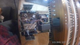
First picture, the dynakit ST120 overview with fan accessory, one AX6 board top, one dyna PC15 with djoffe idle current control accessory board bottom.
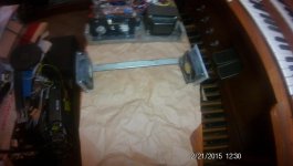
Second picture, the fan accessory removed from under the amp. Two PCAT power supply fans run at 9 v instead of 12 v nominal, from a wall transformer.
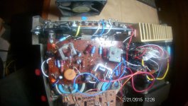
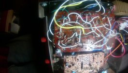
Third picture, the point to point AX6 board, component side. Nema CE laminate.
Fourth picture, the point to point AX6 board, wire side.
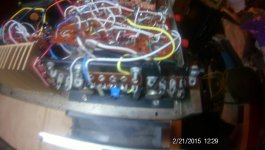
Fifth picture,left the OT current test points, middle the idle bias diode stack & pot, right a ground test point, mounted on top of the OT flange.
Fifth picture, the 80v to 70 V regulator for both channels. Replaces dynakit PC14. That is old Pentium II CPU heat sink; I can't buy more of these.
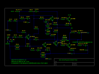
Sixth picture, the AX6 schematic as modified by me to center the output quiet voltage 1/2 of regulated supply voltage, for best 2nd harmonic minimization. Also the 68 pf input cap kills radio stations from coming in on the 3 m RCA cables from the RA88-modified mixer.
New AX6 is very quiet idle, quite loud on the 8 ohm SP2-XT speakers when signal calls for it. Overall sound very good.
dynaco PC15 board with djoffe bias mod is slightly better sounding on high bell on LST-7415 Martin Denny Golden Hawaiian Hits band 5 the Hukilau song. I'll investigate replacing AX6 VAS D44-R2 and drivers TIP41C-42C with faster transistors with lower Cob when I get another amp running reliably. And cut up some TV's for color deflection drivers, I can't buy these 2SC-2SA numbers except from e-bay (real or not?). The 2SC3423 and 2SA1837 I bought from Newark & Mouser turned out to be *****ese clone house instead of sanyo or toshiba, and in F packages with no heat sink tabs.
The beautiful heat sink posted previously by Mr. Finch is not available here from major distributors like Newark(farnell) or mouser. That wouldn't fit in my chassis anyway. Little shops that will sell it might stiff me for $30-40 shipping charge (other do about 25% of the time), so I don't like to use new suppliers. UPS from newark is about $8, mouser $12 minimum.
First picture, the dynakit ST120 overview with fan accessory, one AX6 board top, one dyna PC15 with djoffe idle current control accessory board bottom.
Second picture, the fan accessory removed from under the amp. Two PCAT power supply fans run at 9 v instead of 12 v nominal, from a wall transformer.
Third picture, the point to point AX6 board, component side. Nema CE laminate.
Fourth picture, the point to point AX6 board, wire side.
Fifth picture,left the OT current test points, middle the idle bias diode stack & pot, right a ground test point, mounted on top of the OT flange.
Fifth picture, the 80v to 70 V regulator for both channels. Replaces dynakit PC14. That is old Pentium II CPU heat sink; I can't buy more of these.
Sixth picture, the AX6 schematic as modified by me to center the output quiet voltage 1/2 of regulated supply voltage, for best 2nd harmonic minimization. Also the 68 pf input cap kills radio stations from coming in on the 3 m RCA cables from the RA88-modified mixer.
New AX6 is very quiet idle, quite loud on the 8 ohm SP2-XT speakers when signal calls for it. Overall sound very good.
dynaco PC15 board with djoffe bias mod is slightly better sounding on high bell on LST-7415 Martin Denny Golden Hawaiian Hits band 5 the Hukilau song. I'll investigate replacing AX6 VAS D44-R2 and drivers TIP41C-42C with faster transistors with lower Cob when I get another amp running reliably. And cut up some TV's for color deflection drivers, I can't buy these 2SC-2SA numbers except from e-bay (real or not?). The 2SC3423 and 2SA1837 I bought from Newark & Mouser turned out to be *****ese clone house instead of sanyo or toshiba, and in F packages with no heat sink tabs.
Attachments
Will the AX6 work off 75v supply and if I use 4 output devices instead of 2 ?
Yes
Quote:
Originally Posted by mjona
....why is the bias transistor not fixed to the main heat sink.....
That's a solution for the general problem with thermal compensation for any quasi-complementary design. If you use the heatsink as the reference temperature it won't track the bias correctly - often resulting in a fire-prone amp unless very low bias is used. A common solution is to use the air in the case somewhere near the heatsink but not on it, just as Naim does. As discussed and referenced in the other thread, exact bias for a quasi' doesn't really make much practical difference anyway - it can only offer a compromise of bias current and thermal coefficients that don't encourage thermal runaway.
__________________
Ian
close Quote
Above from the 302454-TGM10 thread
So I guessed right again. As you notice in pictures 3,4,5 of post 212, my voltage spreader diodes are mounted in the air above the output transistors to collapse the bias current gently if the heat sink heats up. They are mounted on a Cinch solder terminal strip, 5 terminals, with the adjustment pot paralleled by a clamp diode .5 Vf in case the pot wiper loses contact. The left 2 terminal strip is the test points for the bias current across a .51 ohm emitter resistor, the right 2 terminal strip is a test point for analog ground.
Last edited:
Was a new 1024 line camera right out of the box and using a LED flashlight.
http://www.mcmelectronics.com/product/DISTRIBUTED-BY-MCM-82-19749-/82-19749
I've recently scored a tiny tripod and will try that.
http://www.mcmelectronics.com/product/DISTRIBUTED-BY-MCM-82-19749-/82-19749
I've recently scored a tiny tripod and will try that.
Last edited:
Hello Mr. Apex , I want to build the amp ( with KD503 , can't decide which transformer to use I have a toroid 26-0-26 Vac 3.5A( 170W ) and a normal transformer 200W or soo 17-0-17 8A ( I can put it in series and have around 70V DC on the first one and 40DC on the second one, the wire on the first one is 1.2 mm, I know 1mm is around 3A, on the second one is 2mm. ) Also which PCB do you recommend ? The schematic in post 1 is the one ?
I've read the whole post but there are lots of PCB's and " mods " and Im a bit confused.
Thanks !
I've read the whole post but there are lots of PCB's and " mods " and Im a bit confused.
Thanks !
Hello Mr. Apex , I want to build the amp ( with KD503 , can't decide which transformer to use I have a toroid 26-0-26 Vac 3.5A( 170W ) and a normal transformer 200W or soo 17-0-17 8A ( I can put it in series and have around 70V DC on the first one and 40DC on the second one, the wire on the first one is 1.2 mm, I know 1mm is around 3A, on the second one is 2mm. ) Also which PCB do you recommend ? The schematic in post 1 is the one ?
I've read the whole post but there are lots of PCB's and " mods " and Im a bit confused.
Thanks !
Use 70V DC
Regards
- Home
- Amplifiers
- Solid State
- Retro Amp 50W Single Supply