HI!
Anyone here that have tried this Borbely Tube-MOSFET opamp as a line amp?
I have just built it but have had several problems with it and need some help.
1) One of the ECC86 tubes are almost imposibble to adjust for zero DC. I had to change one of the 100 ohm resistors connected to Rp to have it in balance (changed one of them to 50 ohms).
2) I do not get enough "swing" of out it. Feeding the non-inverting input (R9) through a 10K resistor with a 22p parralled to output should give a me gain of 20db. I need more though. Can't drive my poweramp with this setup
3) Even with a regulated DC filament PSU using the LT1086, I have too much 50 Hz hum.
Anyone who can help me?
Best,
Peter
About the circuit:
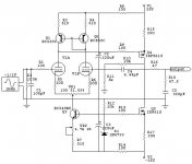
Erno Borbely's hybrid design is both low voltage (+/- 24 volts) and DC-coupled. The differential input stage uses a single ECC86/6GM8 dual triode, which has a maximum anode voltage of 25V (a good substitute is the 6DJ8/ECC88). The current mirror Q1 and the constant current diodes (D1A and D1B) increase the CMRR and improve linearity.
The output stage is a P-channel MOSFET configured as a common source amplifier with Q3 as its current source (the bias current is 10mA and can be adjusted by varying Rs). Rp is adjusted for 0 output voltage.
C2 provides phase compensation and if the opamp is configured for less than 6dB of gain, the R15-C5 low pass network must be added for stability (for G = 6dB, C5 = 100pF; for G = unity, C5 = 330pF). The open loop characteristics of the Borbely hybrid are excellent, especially for a tube opamp: G ~ 53dB, Fh ~ 90kHz and THD < 1%. When set to a gain of 10 (Rf = 10K ohms, Rin = 1.1K ohms), the specs once again are excellent: Fh > 700 kHz, THD < 0.1% and the output impedance is 50 ohms.
Anyone here that have tried this Borbely Tube-MOSFET opamp as a line amp?
I have just built it but have had several problems with it and need some help.
1) One of the ECC86 tubes are almost imposibble to adjust for zero DC. I had to change one of the 100 ohm resistors connected to Rp to have it in balance (changed one of them to 50 ohms).
2) I do not get enough "swing" of out it. Feeding the non-inverting input (R9) through a 10K resistor with a 22p parralled to output should give a me gain of 20db. I need more though. Can't drive my poweramp with this setup
3) Even with a regulated DC filament PSU using the LT1086, I have too much 50 Hz hum.
Anyone who can help me?
Best,
Peter
About the circuit:
Erno Borbely's hybrid design is both low voltage (+/- 24 volts) and DC-coupled. The differential input stage uses a single ECC86/6GM8 dual triode, which has a maximum anode voltage of 25V (a good substitute is the 6DJ8/ECC88). The current mirror Q1 and the constant current diodes (D1A and D1B) increase the CMRR and improve linearity.
The output stage is a P-channel MOSFET configured as a common source amplifier with Q3 as its current source (the bias current is 10mA and can be adjusted by varying Rs). Rp is adjusted for 0 output voltage.
C2 provides phase compensation and if the opamp is configured for less than 6dB of gain, the R15-C5 low pass network must be added for stability (for G = 6dB, C5 = 100pF; for G = unity, C5 = 330pF). The open loop characteristics of the Borbely hybrid are excellent, especially for a tube opamp: G ~ 53dB, Fh ~ 90kHz and THD < 1%. When set to a gain of 10 (Rf = 10K ohms, Rin = 1.1K ohms), the specs once again are excellent: Fh > 700 kHz, THD < 0.1% and the output impedance is 50 ohms.
Attachments
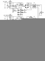
This is the regulated DC fillament supply I use. I only uses PSU for both ECC86 tubes. Do I need one separate for each channel?
Ground is not connected to the case. Should it be? Have a lot of 50 Hz hum comming through.
I'm not using the 10.000uf caps at the output(C16), but two parralled 2200uf instead.
Ground is not connected to the case. Should it be? Have a lot of 50 Hz hum comming through.
I'm not using the 10.000uf caps at the output(C16), but two parralled 2200uf instead.
Attachments
You may be get some mistake circuit !!!
You may be get some mistake circuit !!!
After I build this circuit I can set 0V DC output easier and I don't match other device and I instead transistor constant current circuit for constant current diode")
I use AC voltage for bias filaments but I don't get hum on output ???
If you wanna get a lot of my pictures you can email to me all time
Regard
AHT
You may be get some mistake circuit !!!
After I build this circuit I can set 0V DC output easier and I don't match other device and I instead transistor constant current circuit for constant current diode
I use AC voltage for bias filaments but I don't get hum on output ???
If you wanna get a lot of my pictures you can email to me all time
Regard
AHT
Attachments
Ok, ground the case(s).
Swap the tubes from channel to channel.
IF the problem *switches* channels - it is the tube.
IF not, it is a wiring error.
The lack of DC balance is a clue.
Are you seeing approximately the same voltage at the gates of the mosfets??
You can't drive your amps with 20dB of gain??
Your amps should drive fine with just the output of a CD player or
any other line level audio device (tuner, tape player, etc..).
No gain.
So, obviously something is wrong.
Possibly you don't have a ground reference at the output for the gain stage??
_-_-bear
Hi AHT!
I am also building the Hybrid line stage and hopefuly it will be ready in couple of weeks.
I made the original PCB and use the J508 CCS diode, but I saw your design and I would like to ask: could you post your PCB design and schematic? The original PCB is not the best quality and your with the discrete CCS is much nicer and more practical!
How do you like the sound?
Do you use as preamp or only like buffer?
Could it use as preamp for the ZEN amp?
Thanks and greets:
Tyimo
UltimateX86 said:it can be modified for balanced?
thx
no idea ?
bear said:Ok, ground the case(s).
You can't drive your amps with 20dB of gain??
Your amps should drive fine with just the output of a CD player or
any other line level audio device (tuner, tape player, etc..).
No gain.
So, obviously something is wrong.
The gain is normally 20dB, but can be reduced by changing the feedback
Tyimo said:Hi AHT!
could you post your PCB design and schematic?
Tyimo
+1
Banned
Joined 2002
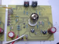
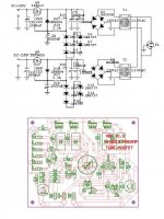
Ok...following PCB
This is PCB please see schematic for insert other device.
It's can be use for line preamp, opamp, poweramp (channge power mosfet to IRF540& IRF9540.
My article is THAI language I don't translate to ENGLISH. But you can tell me in this post all time.
It's can be use input balance by edit some circuit in feedback stage.
Regard
AHT
Attachments
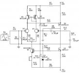
This is schematic.
I seen some website for modified diode to transistor circuit so I had used this circuit 1-2 years ago. It's look great design & good stability.
I had used +/- 24V and now increase to +/-35V for high gain and use 6DJ8/ECC88 instead 6GM8/ECC86
Regard
AHT
I seen some website for modified diode to transistor circuit
so I had used this circuit 1-2 years ago. It's look great design & good stability.I had used +/- 24V and now increase to +/-35V for high gain and use 6DJ8/ECC88 instead 6GM8/ECC86
Regard
AHT
Attachments
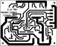
I'd forgot TOP OVERLAY
Sorry for waiting.
On the output mosfet you don't paralell it. But you can paralell it when you only use this schematic for poweramp single end by use IRF540/9540 instead IRF610/9610 and change Rload from 200 to 0.33*4 (basic paralell power output)
Regard
AHT
Sorry for waiting.
On the output mosfet you don't paralell it. But you can paralell it when you only use this schematic for poweramp single end by use IRF540/9540 instead IRF610/9610 and change Rload from 200 to 0.33*4 (basic paralell power output)
Regard
AHT
Attachments
I had forgot SUPPLY & TOP OVERLAY
Sorry for waiting.
Power supply PCB is comming soon (finding themfor a few days) now you can hardwire for your prototype
On the output mosfet you don't paralell it. But you can paralell it when you only use this schematic for poweramp single end by use IRF540/9540 instead IRF610/9610 and change Rload from 200 to 0.33*4 (basic paralell power output)
Regard
AHT
Attachments
- Status
- This old topic is closed. If you want to reopen this topic, contact a moderator using the "Report Post" button.
- Home
- Amplifiers
- Solid State
- Borbely low-voltage hybrid Tube-MOSFET opamp as a line amp...