the mosfet hitachi becomes expensive.. .
thus as aht I would like to test the IRF9610 and 610 which are often on 30V
-----
edit
-----
you spoke about the tubes....
http://www.borbelyaudio.com/eb804421.asp
http://digilander.libero.it/paeng/projects_frame.htm
thus as aht I would like to test the IRF9610 and 610 which are often on 30V
-----
edit
-----
you spoke about the tubes....
http://www.borbelyaudio.com/eb804421.asp
http://digilander.libero.it/paeng/projects_frame.htm
Hi AHT!
Where did you connect the 9th pin of the tube: to the signal or to the power grund or to the case?
How did you make the tube heater PSU? Passiv or regulated, DC or AC?
Greets:
Tyimo
Where did you connect the 9th pin of the tube: to the signal or to the power grund or to the case?
How did you make the tube heater PSU? Passiv or regulated, DC or AC?
Greets:
Tyimo
BE Hybrid with 20dB gain
Hi!
After 1 year I am back again to ask a question! 🙂)
I would like to use the BE Hybrid line amp with the maximum gain settings (20dB).
I know that in this situation the R9= 1.1K, but need I install the R15-C5 network in the output too?
What kind of wolume pot would be the best?
In the input or on the out put? How many K ohms?
greets:
Tyimo
HI!
Anyone here that have tried this Borbely Tube-MOSFET opamp as a line amp?
I have just built it but have had several problems with it and need some help.
1) One of the ECC86 tubes are almost imposibble to adjust for zero DC. I had to change one of the 100 ohm resistors connected to Rp to have it in balance (changed one of them to 50 ohms).
2) I do not get enough "swing" of out it. Feeding the non-inverting input (R9) through a 10K resistor with a 22p parralled to output should give a me gain of 20db. I need more though. Can't drive my poweramp with this setup
3) Even with a regulated DC filament PSU using the LT1086, I have too much 50 Hz hum.
Anyone who can help me?
Best,
Peter
About the circuit:
Erno Borbely's hybrid design is both low voltage (+/- 24 volts) and DC-coupled. The differential input stage uses a single ECC86/6GM8 dual triode, which has a maximum anode voltage of 25V (a good substitute is the 6DJ8/ECC88). The current mirror Q1 and the constant current diodes (D1A and D1B) increase the CMRR and improve linearity.
The output stage is a P-channel MOSFET configured as a common source amplifier with Q3 as its current source (the bias current is 10mA and can be adjusted by varying Rs). Rp is adjusted for 0 output voltage.
C2 provides phase compensation and if the opamp is configured for less than 6dB of gain, the R15-C5 low pass network must be added for stability (for G = 6dB, C5 = 100pF; for G = unity, C5 = 330pF). The open loop characteristics of the Borbely hybrid are excellent, especially for a tube opamp: G ~ 53dB, Fh ~ 90kHz and THD < 1%. When set to a gain of 10 (Rf = 10K ohms, Rin = 1.1K ohms), the specs once again are excellent: Fh > 700 kHz, THD < 0.1% and the output impedance is 50 ohms.
Will it possible hardwire the circuit? Also, is the op amp critical to this circuit since this is functioning as servo?
wow - from 2006!!
Sure you can point-to-point wire it. Why not?
Op amps for servo usually not critical... some prefer jfet input for higher Z... less leakage... but that isn't terribly important.
_-_-bear
Sure you can point-to-point wire it. Why not?
Op amps for servo usually not critical... some prefer jfet input for higher Z... less leakage... but that isn't terribly important.
_-_-bear
HI!
Anyone here that have tried this Borbely Tube-MOSFET opamp as a line amp?
I have just built it but have had several problems with it and need some help.
1) One of the ECC86 tubes are almost imposibble to adjust for zero DC. I had to change one of the 100 ohm resistors connected to Rp to have it in balance (changed one of them to 50 ohms).
2) I do not get enough "swing" of out it. Feeding the non-inverting input (R9) through a 10K resistor with a 22p parralled to output should give a me gain of 20db. I need more though. Can't drive my poweramp with this setup
3) Even with a regulated DC filament PSU using the LT1086, I have too much 50 Hz hum.
Anyone who can help me?
Best,
Peter
About the circuit:
Erno Borbely's hybrid design is both low voltage (+/- 24 volts) and DC-coupled. The differential input stage uses a single ECC86/6GM8 dual triode, which has a maximum anode voltage of 25V (a good substitute is the 6DJ8/ECC88). The current mirror Q1 and the constant current diodes (D1A and D1B) increase the CMRR and improve linearity.
The output stage is a P-channel MOSFET configured as a common source amplifier with Q3 as its current source (the bias current is 10mA and can be adjusted by varying Rs). Rp is adjusted for 0 output voltage.
C2 provides phase compensation and if the opamp is configured for less than 6dB of gain, the R15-C5 low pass network must be added for stability (for G = 6dB, C5 = 100pF; for G = unity, C5 = 330pF). The open loop characteristics of the Borbely hybrid are excellent, especially for a tube opamp: G ~ 53dB, Fh ~ 90kHz and THD < 1%. When set to a gain of 10 (Rf = 10K ohms, Rin = 1.1K ohms), the specs once again are excellent: Fh > 700 kHz, THD < 0.1% and the output impedance is 50 ohms.
HI All
Just wondered what type of diode is the one going to the 100 ohm pot wiper-with 4.7mA going thru it
With a lot of research and friend's help, I recently built the 4sUniversal tube preamp and lastly modded the 12au7 Bravo low voltage tube/mosfet hybrid headphone amp. To say I am impressed with the modded Bravo headphone amp mated to a pair of Grado phones would be an understatement.
If I could just get that sound in a line stage.
Rummaging through the net and ran across this; 'Borbely balanced tube input mosfet output linestage single ch preamplifier PCB !' from Jim's Audio. It is a low voltage tube/mosfet hybrid similar to the Bravo. Have to try it.
Trying to learn but far, far from an engineering type. Apologies for the newbness.
How do I go about building, or sourcing, a suitable +/-24 volt power supply and what volume pot and where does the vol pot go?
Slow, very slow. I am just a beginner and had no idea how to cross older NLA parts to newer obtainable parts which forced me to order questionable parts from China sellers on ebay. That turned out bad. Waited over two months for parts which never arrived, nor would the seller, miantaxia-o, refund my money. 😡 So I ditched building the power supply and settled on a bel HAA24-0.6-AG +/-24v linear power supply for the board and a MeanWell 24v smps w/TSRN 1-2465A 6.5v voltage reg. for the tube heater. Hopefully this works out.
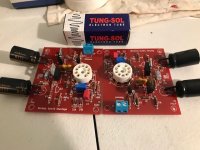
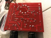
Here's the board. Ordered mini pc tube sockets instead of regular ones and spread the legs out to reach the solder pads, which of course caused the tube pin sockets to become misaligned. No manner of wiggling and pushing could get a tube to seat. A pair of regular sockets came in today along with more 12au7 and socket savers. Time to desolder/solder the sockets in.
Good thing my soldering skills are improving.
This will go in a wooden box. The bottom and sides are roughed in but not sure where to place the switch/input/output/vol pot. Top would be less work.
It sounds like you had a bad start, and the socket thing sounds like a bad decision.
You can easily obtain both PCB mount noval sockets and chassis mount sockets in all countries, but you of course have to find the right sources.
I can not load the pictures, but it sounds like an interesting projects. Let us hear your opinion how it sounds, when get there.
You can easily obtain both PCB mount noval sockets and chassis mount sockets in all countries, but you of course have to find the right sources.
I can not load the pictures, but it sounds like an interesting projects. Let us hear your opinion how it sounds, when get there.
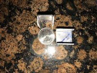
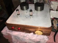
Waiting for the stain to dry on the box so it can be cleared. Poplar sides stained with red mahogany, volume knob from 1.5" pine stained golden pecan, and brushed flat plate aluminum for the top. To make for better visual appeal, will probably mount a couple empty transformers covers on the top plate behind the tubes.
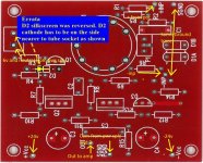
Am I in the ballpark with the connections for 12au7?
+/- vcc _ +/- 24 volt input and com from board power supply.
Out to amp _ +audio to amp. Use this plus SGND/PGND for audio outputs to amp?
6v and neutral from heater supply _ looking at the schem I assume the board is configured to allow 12v series or 6 volt parallel hookup of the heaters (or is this used differently for the 6gm8?). Using 6v, and 12au7, both of these inputs will be +6v and since pin9 is center tap, the neutral side of the heater power supply is the hole marked -inp. Not sure of this but the trace does fall back to pin9.
+inp _ +audio input to board from potentiometer.
SGND _ ground or shield from potentiometer. Bring input shield wire from potentiometer to this point?
Trace from SGND also runs to pin just below -inp, does this pin also need to go to ground or is this asking for ground loops if also running this point to ground?
Pin just above -inp lettering goes to R9 with ties in with pin7 (grid) and R8/C2 (what doe this filter do?). What is this pin for? What does it connect to, or should it?
Attachments
Just had one of those duh moments. Time to regroup.

From Jims Audio add copy; The input tube can be the popular ECC86/6GM8 or E88CC.
Nothing there about using a 12au7 but it does say; The input can be configured as either balanced input, or unbalanced input.
How do I go about configuring it for unbalanced input?
From Jims Audio add copy; The input tube can be the popular ECC86/6GM8 or E88CC.
Nothing there about using a 12au7 but it does say; The input can be configured as either balanced input, or unbalanced input.
How do I go about configuring it for unbalanced input?
Last edited:
In+ and in- are the balanced input, simply connect in- to SGND for single input
The two TO220 mosfet will probably need some heatsink...
To use that as a preamp, take great care to protect your amp. As Borbely mentionned in the Hybrid HP article, you need to take care to start the heater 6.3V first, let the tube warmup, and then apply the +-24V supply, otherwise the circuit feedback is not working at startup and a large dc volt swing will happen at the output.
Or use a startup output mute relay with delay and/or use an output coupling cap to cut the dc...
Or (more dangerous) start your amp only once the preamp is stabilized, but if you go this way, Never forget to do it this way, or if your amp is dc coupled, you can damage your speakers...
Personally I prefer safe to sorry and I would implement the correct startup procedure, and use a mute relay...
SB
Last edited:
It has two switches, one for heater supply and the other for board supply. With tube gear, it's become a habit of letting it warm before powering up the amps. I'll have to learn how to add a mute relay but an output cap is doable immediately.
I'm guessing no larger than 2.2uf for the output cap?
Since the tubes will be protruding through the top aluminum plate, the room for heatsinks is rather small. Should this be enough heatsinking? I can add to their length but not height.
I'm guessing no larger than 2.2uf for the output cap?
Since the tubes will be protruding through the top aluminum plate, the room for heatsinks is rather small. Should this be enough heatsinking? I can add to their length but not height.
Attachments
- Home
- Amplifiers
- Solid State
- Borbely low-voltage hybrid Tube-MOSFET opamp as a line amp...