Nice to see someone else getting useful results out of this. I use the laser printer/UV transfer method and it works brilliantly.
I bet you can't wait to hook it up to the proper amp 😀
I bet you can't wait to hook it up to the proper amp 😀
Hi Mooly, nice job on the boards. I still haven't gotten around to trying out the other versions without the photovoltaic optoisolators, my "real life" keeps getting in the way of fun. 🙁 Your comments about the performace of these using the photovoltaic devices confirms my experience with them, they seem to do the job well, I've never had any trouble or noticed them running warm at all.
I'm wondering if anyone here has the facilities to check the possible release time issues, I've never had any problem, but it would be nice to see some actual data, my scope died and I don't have the funds to fix or replace it right now. When I did test them years ago, I didn't even think about checking release time as it pertained to MOSFET survival, just figured it was certainly faster than a mechanical relay and moved on.
Mike
I suppose I could test the release time somewhat, but not with the current implementation. One of my amplifiers has a complex protection scheme (as of yet unfinished) and I should be able to compare the trigger point when the protection trips to the actual disconnecting of the load. This might not happen for a couple of weeks yet and my scope cannot freeze-frame an image so it'd be an educated guess, but that's better then nothing right? 😀 My guess is that it would also be much faster then a mechanical relay, so I'd move on too, but as I'll be scoping the amp when finalising the protection it wont exactly be hard to test one more thing.
Regarding the destruction of the FETs under a reactive load under a fault condition.
From post 223

The FETs that I linked to have an avalanche energy of 120mJ for a single pulse, which is considerably under your 224mJ calculation. However 5.1mH seems quite high for most applications and I suppose the end application does somewhat dictate what size FETs you would use in the amplifier. In my active setup the woofers have around 1mH inductance with the tweeter and mid having negligible amounts, so it would appear that in my situation the FETs would survive. Not to mention 40 volt rails.
Certainly if you were powering a massive sub with a huge Le then I'd guess it'd be an issue. Although with rail fuses any sub worth it's salt will easily survive a second or two at the rail potential.
For a higher power application you could use something like an FP4568, not cheap, but then again most people don't use that many channels of high power amplification. And at those kind of rail voltages you'd need some ridiculously priced relay to ensure safe switching during a fault.
Regarding the destruction of the FETs under a reactive load under a fault condition.
From post 223
The FETs that I linked to have an avalanche energy of 120mJ for a single pulse, which is considerably under your 224mJ calculation. However 5.1mH seems quite high for most applications and I suppose the end application does somewhat dictate what size FETs you would use in the amplifier. In my active setup the woofers have around 1mH inductance with the tweeter and mid having negligible amounts, so it would appear that in my situation the FETs would survive. Not to mention 40 volt rails.
Certainly if you were powering a massive sub with a huge Le then I'd guess it'd be an issue. Although with rail fuses any sub worth it's salt will easily survive a second or two at the rail potential.
For a higher power application you could use something like an FP4568, not cheap, but then again most people don't use that many channels of high power amplification. And at those kind of rail voltages you'd need some ridiculously priced relay to ensure safe switching during a fault.
No need. Just clamp the output side of the MOSFET speaker relay with catch diodes to each rail. The diodes need only be rated for the peak repetitive current.
Nice input Mooly and a good result.
Thanks Bonsai 🙂
Nice to see someone else getting useful results out of this. I use the laser printer/UV transfer method and it works brilliantly.
I bet you can't wait to hook it up to the proper amp 😀
Yep, that's the next step... probably the hardest bit as the amp wasn't built to come apart in a hurry.
Hi Mooly, nice job on the boards........
I'm wondering if anyone here has the facilities to check the possible release time issues, I've never had any problem, but it would be nice to see some actual data...........
Mike
Thanks Mike,
I agree that the photovoltaic couplers are definitely the way to go on this.
Release times... maybe if I have the time and inclination I might cobble a little test together.
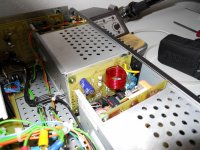
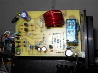
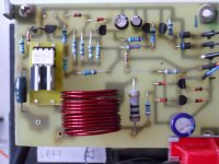
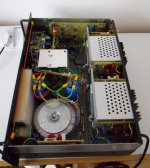
Well the SS relays have just been fitted... time consuming but pleased to report all has gone well.
In the pictures you'll notice a cap (220uF) just below the relay. That had to be removed as it's purpose was to charge to +48 volts at switch on ensuring the relay closed with a definite action the voltage then reducing to give around 50% of the coil voltage. Good news was that the resistor values were spot on and give an LED current of 13milliamps... perfect.
So there we have it 🙂
Attachments
Thanks Andrew...
Have to say it all sounds very good too. I'm reluctant to say better ! but it just could be because I do tend to listen at what many would consider lowish levels a lot of the time anyway... precisely where the relay issue appears.
Have to say it all sounds very good too. I'm reluctant to say better ! but it just could be because I do tend to listen at what many would consider lowish levels a lot of the time anyway... precisely where the relay issue appears.
Nice work !
I see 2 FETs. Are you switching AC or DC?
AC... it's in the "positive" speaker output from the amp.
I have speed-read the thread, but cannot see the actual schematic?
Speed read fails, see post 22😉
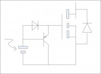
If turn-off time is a concern, would this simple circuit (a diode and a transistor) help draining the gate charge quickly?
That' a classic type of circuit...
I think the turn off time will be orders of magnitude quicker than a relay tbh The photovoltaic coupler has a "quick turn off" circuit incorporated according to the data sheet.
As I mentioned, if I have the inclination I might do a real test.....
That' a classic type of circuit...
I think the turn off time will be orders of magnitude quicker than a relay tbh The photovoltaic coupler has a "quick turn off" circuit incorporated according to the data sheet.
As I mentioned, if I have the inclination I might do a real test.....
It's most likely very much so. However, personally I wouldn't mind putting in a couple extra parts to help discharge the gates despite the internal quick-turn-off circuit. To my understanding if I may, the internal turn-off circuit takes gate charge as its power supply, and it is intended to straddle across the gate capacitance directly. When two of such circuit are connected in series there could be some uncertainty to its behavior unless one knows the details about the quick-turnoff circuit. An extra gate discharge path would then bypass the uncertainty and make it worry-free.
Your idea of making the SSR a drop-in replacement is very cool.
Thanks nattawa,
I understand your thinking on the two cells in series re the turn off uncertainty. We need to measure it to know for sure.
For speaker protection I imagine the integrator time constant of the DC offset detector circuitry will absolutely swamp any small active electronic delays.
This might be of interest...
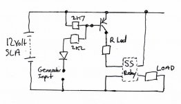
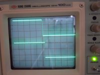
The circuit shown below was used with a SS relay of the type I made yesterday post #267 using the AVAGO coupler with both cells and LED's wired in series.
The LED current was around 13 milliamps for the test.
The load switched by the relay was 100ma. Increasing the load to 2 or 3 amps had no real impact on the on/off times or shape of the switching transitions. All that was observed was a noticeable drop in voltage across the load due to the high Rds of the FET's.
The FET's used were NOT of the type I used before (didn't have any) and were an IRF830 and IRF630.
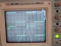
The first shot is a general overview of the switching on and off of the relay when driven at 200hz. At slower speeds the eye can see the transitions are the same but the camera doesn't photograph well at low sweep speeds.
The second shot is a detail of the on time at 0.1millisecond/div. So it takes around over 0.3ms for the FET's to turn fully on. Maybe the gate capacitance charging from the limited drive current available ?
The third shot is a detail of the off time again at 0.1ms/div. So the off time is quick and well defined at around 0.04ms from removal of the LED drive.
The circuit shown below was used with a SS relay of the type I made yesterday post #267 using the AVAGO coupler with both cells and LED's wired in series.
The LED current was around 13 milliamps for the test.
The load switched by the relay was 100ma. Increasing the load to 2 or 3 amps had no real impact on the on/off times or shape of the switching transitions. All that was observed was a noticeable drop in voltage across the load due to the high Rds of the FET's.
The FET's used were NOT of the type I used before (didn't have any) and were an IRF830 and IRF630.
The first shot is a general overview of the switching on and off of the relay when driven at 200hz. At slower speeds the eye can see the transitions are the same but the camera doesn't photograph well at low sweep speeds.
The second shot is a detail of the on time at 0.1millisecond/div. So it takes around over 0.3ms for the FET's to turn fully on. Maybe the gate capacitance charging from the limited drive current available ?
The third shot is a detail of the off time again at 0.1ms/div. So the off time is quick and well defined at around 0.04ms from removal of the LED drive.
Attachments
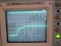
Is it worth checking SOA at turn ON when using these as supply rail relays?
0.3ms is a significant proportion of 1ms SOA at turn on.
The OFF seems to be adequately fast, ~40us delay and then a switching period <<10us.
0.3ms is a significant proportion of 1ms SOA at turn on.
The OFF seems to be adequately fast, ~40us delay and then a switching period <<10us.
Last edited:
I wonder if it might make sense to wire the AVAGO outputs in parallel to reduce switching times, the data sheet for the PVI5013 says "The dual-channel configuration allows its outputs to drive independent discrete power MOSFETs, or be connected in parallel or in series to provide higher-current drive for power MOSFETs or higher-voltage drive for IGBTs." It could be a better way to go.
Mike
Mike
The DC detect circuit I experimented with last year ( The Members thread shows LT spice sims), had a variable delay in sending a trigger signal that was inversely proportional to the output offset level.
Low offset took a long time, whereas a high offset took a much shorter time.
This fast output relay could respond adequately to protect any speaker from DC output offset, whatever the cause.
Low offset took a long time, whereas a high offset took a much shorter time.
This fast output relay could respond adequately to protect any speaker from DC output offset, whatever the cause.
- Home
- Amplifiers
- Solid State
- Output Relays