Compared to the 4-transistor Archosaurus, it looks complex, but most of the additional actives are just signal semiconductors, and the result is an adjustment-free amplifier, needing no thermal couplings.Few things I learned:
a) Circlophone is not "little" - it actually has 'normal' number of components/devices, especially when compared with 'prehistoric' kinds of amps
Its performances are also vastly superior
Yes, transformer, heatsinks, reservoir caps and case are the most expensive parts of an amplifier, but since the C is not picky about the components, it is generally possible to recycle a number of partsb) it's also not "cheap" - especially heatsinking. Unless one happens to have drawers full of old stuff (like original 2N3055s) and scarps of thick Alu profiles gathering dust in the garage
The quiescent normally establishes itself somewhere between 150mA and 300mA.c) "warm" class AB actually means "very hot" class AB. Good thing winter is coming soon.
d) my PCB design assumed much cooler temperatures, otherwise I would mount all transistors on the main heatsink.
Your 270mA is therefore in the range, a bit on the high side, and with 100V total supply, this means 27W/channel of quiescent power, certainly not negligible, but if you think it's bad, imagine what it would be for a full class A amplifier running from the same rails.....
You can safely reduce the quiescent current if you need to by increasing R21, or reducing the set current of the CCS playing its role.
200mA would already make a difference, and should have no audible effect, except the pure class A range will be slightly reduced
A bit too hot for comfort, and unfortunately your options are limited: decrease the supply voltage or increase the sink sizeWith both channels running for 3 hours (idle), with rails 50V, temperature of the heatsink (drivers + vas) rises to 83 C.
That's perfectly OK: warm class AB, but if you want, you can reduce it by modifying the IqMain heatsink for output transistors runs at 50 C.
A thermocouple inserted in a small hole would give much more reliable measurementsNot sure if my infrared termometer works correctly - it gives higher temperature readings on black/dark surfaces, and lower readings on shiny aluminum surfaces..
83 degrees is measured on black anodized clip-on heatsinks.
Agreed. The sound quality, in my brief testing, with medium size speaker, was great.Compared to the 4-transistor Archosaurus, it looks complex, but most of the additional actives are just signal semiconductors, and the result is an adjustment-free amplifier, needing no thermal couplings.
Its performances are also vastly superior
When idle - no hum, no nothing! This the quietest amp so far I built.
And the idea of self-adjustment in real-time is great, even if it comes at the (small) cost of few extra devices.
Next step for me - get PSU with lower rail voltage.
All my amps, so far, were built for my +/-50V external psu - no need to spend money on the PSU for each of them, so I have only one PSU in its own enclosure, and a stack of several amps to choose from
")
Now I need slightly smaller PSU. Will try SMPS +/- 35V.
Thanks Elvee for the great design.
Funny you too made that observation, and welcome to the club:When idle - no hum, no nothing! This the quietest amp so far I built.
Unexpected noise benefits of the Circlophone topology?
Practically all the builders of the C made that observation independently, and it is not something evanescent or subjective, unlike say, the "warmness" of the sound, or its "roundness": the noise is audible or it is not, and it's not an isolated remark as most of the builders made the same, without being asked or prompted, meaning it becomes statistically significant.
Since the quality of the components has nothing to do with it (many different types of semi's have been used throughout the world), the only possible explanation has to be related to the topology, probably the real-time servo of the "vertical" (Iq) loop.
All amplifiers rely on a "horizontal" (signal) feedback loop, and the C is no exception.
This loop reduces the THD and other perturbations appearing within the loop, and in the C, the other loop is orthogonal and should have no direct effect on the signal.
My guess is that the servoing of the Iq from end to end also removes the common-mode noise, and since the noise in a pair of devices (like the OP) is not correlated, some of this CM noise spills into the signal.
If the CM noise is made smaller initially, the same proportion will also be smaller
A bit too hot for comfort, and unfortunately your options are limited: decrease the supply voltage or increase the sink size
I'll leave this build as is, to be powered by 35V rails, but since I have more PCBs made, and all the parts needed in abundance, I'll quickly build one more circlo, with fan cooling and temp sensing fan controller.
Will also allocate more space for driver's heatsink
Hello friends,
I have built and used multi-channel LM3886 amp which served as 5 channel setup, a Toshiba 2SA1943 / 2SC5200 based mono clone of Marantz MA 9S2 which mainly drives the sub woofer and TPA3118 based ALLO volte+ D class stereo amp which currently drives the front stereo pair.
My speakers are three Boston Acoustics A26 bookshelf which I use as front stereo and center channel and have a pair of DIY speakers for rear channel. Audio source is PC with Asus Xonar D2X soundcard. Stereo speaker amp is always powered on during most of the time of the day.
Now looking to build a stereo class AB to drive the front stereo A26 and want to know how this circlophone amp will fair against all of the above amps in terms of audio quality and loudness:-
DAC - Elvee's Circlophone - Power Amplifier
I am looking to use a 23-0-23 transformer to drive the new build.
Last edited:
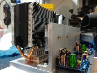
Here it is: more beefy circlophone with bigger heatsinks for drivers/VAS,
and 2 active fans with heatpipes (speed controlled by temp sensor).
Output transistors (MJL21194) are mounted on the main aluminum plate (0.75inch thick), directly under heatpipes.
If this setup runs too hot, I guess the only solution remaining is liquid nitrogen
cooling
I'm OK with temperatures up to 60 degrees C when idle.
I'll leave this build as is, to be powered by 35V rails, but since I have more PCBs made, and all the parts needed in abundance, I'll quickly build one more circlo, with fan cooling and temp sensing fan controller.
Will also allocate more space for driver's heatsink
Attachments
I've been testing bigger circlophone for the whole day.
Since it was built exactly the same as the first one, it also sounds the same.
Which means GREAT. Definitely the best amp I ever heard (again).
Runs COLD now. Fans are barely moving (very quiet!), and all transistors
are at approx human's body temperature.
For some reason, it draws more current than 1st version, when idle.
If it's more in the A-class zone, that's fine with me..
Differences between previous build and this one:
a) Added: 2 fans + fan controller + Lm2596hv (50V ==> 12V)
b) Q50 (CCS replacement for R21) is 2N5551 instead of KSC1845
c) R17 is 2 x 4k7 instead of 10k (didn't have 10k 0.5W, and 0.25W runs hot)
d) output transistors are MJL (plastic) instead of MJ (TO-3)
Conclusion? I don't see much sense now in building any other amps.
Circlophone is so EASY to build. Just solder all the parts, and voila - plug in speakers blindly, and it's gonna work. No need for any adjustments, measurements, etc.. Don't even bother with speaker protection
The quality of sounds it delivers is unbeatable.
Rich bass, all frequencies perfectly present; I didn't even know my speakers were so good (JBL studio 590).
So, question to Elvee - is it possible to make Circlophone BIGGER?
More power, more output transistors?
Not that it's rally needed, but what the heck..
Good: that's exactly what it had been designed forI've been testing bigger
/ ..... /
for any adjustments, measurements, etc
Don't be overconfident: the C is probably safer than many other amps thanks to its servo, but it is certainly not immune to component failures, mishaps, etc... Don't even bother with speaker protection
Speaker are expensive, and it's really worth protecting them
I always resisted the idea, mostly for two reasons: the idea behind the C concept is being able to build an excellent discrete amplifier just by gathering some random (not too random though), junk grade parts, and soldering them together in the right order.So, question to Elvee - is it possible to make Circlophone BIGGER?
More power, more output transistors?
No need for special components, matching, thermal coupling or even measurements: it can be built without even a basic multimeter (not something I recommend).
As soon as you use multiple output pairs, you will need either a stringent matching + excellent thermal coupling between // transistors, or significant emitter resistors for balancing.
In reality, a bit of all three probably.
This requires more competency from the builder (which you obviously have), and emitter resistors, which are going to slightly blunt the sharpness of the CFP's.
A possible solution would be very high power transistors: 5 or 10 years ago, transistors having a collector dissipation of 400W or 500W appeared on the market.
I think they were MG-something or MT-something. Other members probably have a better recollection than mine.
They would allow 200W to 300W output, depending on the safety margins you allow yourself.
If you are intent on paralleling devices, I think I may have a solution, using absolutely minimal balancing resistors without compromising safety or performance.
It won't be as accessible as the original C, because thermal aspects would still need to be cared of properly, and matching would be necessary, but no one can embark on a 1kW design without minimal competencies.
I am not worried about you, but other members might think they could upgrade their 60W circlo into a 600W one using the same methods, with disaster as an end result.
I shall seriously examine the problem, and if I find a satisfactory solution, I will publish it here.
After all, the C has been built with MOSFETs, Darlingtons, and even germanium transistors, and it should be upgradable for power too
Thanks for the answer. That reminds me about Mosfet circlophone.
It's easier in the sense that drivers are not needed in this case (less problems with cooling), and Mosfets are cheap compared to MJs.
Quality wise - Does mosfet version sounds as good as BJT?
I think I'll try it, have drawers full of IRFP260s available
Question about bridging:
Is it better to drive 1/2 of the bridged amp from the output of the other half, like you shown in your "circlophone bridging example" earlier in this thread,
OR
is it better to add 1 or 2 op-amps driving both halves with inverted/non-inverted signal?
By "better" I mean lower distortion.
In your example of bridged circlophone, output signal from one amp was fed to the junction between R16 and C3, and C3/R16 need to be swapped (up/down).
I guess it might be an option to feed this signal directly to the base of LTP's Q3 ?
I already have boards made, and don't want to change them..
I’ve seen some IGBTs with insanely high SOA lately. Not the fastest things on the planet, designed for solar inverters at maybe 10kHz switching frequency. 300 to 600 watt, and according to the SOA graphs, purely TJ limited with no second breakdown. Not sure if I believe that but maybe somebody has som experience with them. If they live up to the specs they may be what you need for a high power C or anything else where you can’t stand paralleling devices.
mosfet circlophone
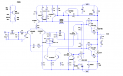
Elvee, can you confirm if this schematic of Mosfet circlophone is correct?
All mosfet circlophone schamatics I found in the forum, are 'upside down' schematics, and got me confused
Not sure if I got it right here...
Perhaps 390Ohm resistors should go BEFORE gate stoppers, not after?
http://www.slowbears.com/tmp/circlo_mosfet2.jpg
Sounds like a good planIf they live up to the specs they may be what you need for a high power C or anything else where you can’t stand paralleling devices.
NoElvee, can you confirm if this schematic of Mosfet circlophone is correct?
Yes, because they use NMOS: that's the opposite polarity of the CFP's in the regular C.All mosfet circlophone schamatics I found in the forum, are 'upside down' schematics, and got me confused
You could in principle use PMOS, but they are rarer, less effective and more expensive.
The sensible solution is to reverse all the polarities
In a correct schematic and if you use them, yes, but it preferable to dispense with them: they will introduce a small parasitic pole and eat up some of the stability margin.Perhaps 390Ohm resistors should go BEFORE gate stoppers, not after?
In principle, as the MOS are driven from a high impedance source feeding the 390 ohm, they are not necessary.
If you need to connect the MOS via a significant length of wiring, a better alternative is to thread a ferrite bead on the gate lead
Yes, because they use NMOS: that's the opposite polarity of the CFP's in the regular C.
You could in principle use PMOS, but they are rarer, less effective and more expensive.
The sensible solution is to reverse all the polarities
So I guess it's a "no go" for Mosfet version for me, as I already have PCBs, NPN Vas transistors, etc..., all parts for 'normal' circlophone.
The same goes for IGBTs, I guess.
Perhaps one option would be to retain drivers, and use NMOS with "normal" Circlophone? Would that work?
Maybe drivers wouldn't have to run as hot as for BJTs...
YesThe same goes for IGBTs, I guess.
It could be made to work, but it would be dreadfully ineffective: you would lose an additional +/-6V of output swing, because of the G-S voltage requiredPerhaps one option would be to retain drivers, and use NMOS with "normal" Circlophone? Would that work?
Difficult to predict accurately: in principle, the opamp solution could have a lower distortion, but in reality, there could be a non-linearity compensation between the two halves, cancelling some of the distortionIs it better to drive 1/2 of the bridged amp from the output of the other half, like you shown in your "circlophone bridging example" earlier in this thread,
OR
is it better to add 1 or 2 op-amps driving both halves with inverted/non-inverted signal?
By "better" I mean lower distortion.
I do not see how to combine the feedback and DC stabilization with the signal in an acceptable mannerIn your example of bridged circlophone, output signal from one amp was fed to the junction between R16 and C3, and C3/R16 need to be swapped (up/down).
I guess it might be an option to feed this signal directly to the base of LTP's Q3 ?
Edit:
Here is the link to the bridging circuit:
♫♪ My little cheap Circlophone© ♫♪
Last edited:
I do not see how to combine the feedback and DC stabilization with the signal in an acceptable manner
Edit:
Here is the link to the bridging circuit:
♫♪ My little cheap Circlophone© ♫♪
Yes, that's the circuit I've seen.
How about adding 470uF cap is series with R61, and feed it to the Base of Q18 ? Wouldn't it work?
Here is a link from Rod Elliott showing something similar:
Simplest Ever Bridging Adapter for Amplifiers
Looks like his solution might not be DC stable..
If the cap is in series with R61, it doesn't need to be as large as 470µF, but since the cap already exists, it is simpler to reuse it, but I see your point: you want to use just an identical C for the bridge, and changing the 470µF's position would be difficult.
To avoid doubling the DC offset as in Rod Eliott's circuit, you can add a 22µF cap in series with R61 and make the bridging connection to the base of Q18.
To avoid doubling the DC offset as in Rod Eliott's circuit, you can add a 22µF cap in series with R61 and make the bridging connection to the base of Q18.
If the cap is in series with R61, it doesn't need to be as large as 470µF, but since the cap already exists, it is simpler to reuse it, but I see your point: you want to use just an identical C for the bridge, and changing the 470µF's position would be difficult.
To avoid doubling the DC offset as in Rod Eliott's circuit, you can add a 22µF cap in series with R61 and make the bridging connection to the base of Q18.
Now I'm kind of wondering (it's a general question, not specific to Circlophone):
How will speaker protection circuit work for bridged amp?
I mean I trust circlophone 100%, no offense, but I'd still use speaker protection circuit
Is it OK to detect DC between one of the speaker terminals and the ground?
Or detect DC between speaker terminals (no ground reference) ?
Also - Zobel network (coil) is only needed on one side of the speaker, I guess?
It will be one big *** amp - bridged Circlophone with 50V rails, TO-3 output devices, 3kg of aluminum chassis, and 2 big fans with 4 heatpipes each
One is not sufficient: you need bothIs it OK to detect DC between one of the speaker terminals and the ground?
That could work too, but I am not sure it is going simplerOr detect DC between speaker terminals (no ground reference) ?
In principle, yes, but I wonder how it would behave on a very long cableAlso - Zobel network (coil) is only needed on one side of the speaker, I guess?
- Home
- Amplifiers
- Solid State
- ♫♪ My little cheap Circlophone© ♫♪