Hi,
Hopefully this is a simple question - in the latest book, page 88, Figure 4.1, the feedback resistors R7 and R8 are rated at 1watt each.
When i run a simulation of a similar amplifier, using resistors with a much lower resistance, approx 10x less, but still similar ratio to one another, only then does the power rating meet or slightly exceed the 1watt rating.
Therefore, what is the reason for such a power rating for the feedback resistors given that they are higher in resistance requiring less than 120mW peak power for the highest resistance power ?
Thanks and regards,
Shadders.
see p370, 16.7 Resistor DistortionTherefore, what is the reason for such a power rating for the feedback resistors given that they are higher in resistance requiring less than 120mW peak power for the highest resistance power ?
Well, maybe you can look at some yourself, including DVD/CD combo players and see how well assumptions that nothing exists within amplifier BW is out there to be amplified by PA gain.
Sometimes there have been idle tones just there all the time within audio band and only 65 dB down, for example. Whats that doing there?
View attachment 788577
here you see an idle tone. Then afterwards some Stuff comes thru. Also well within some amps BW. [ Note the measurement BW is 1KHz to 1 MHz log.]
I have lots of this stuff that should not be there IS there.
To the degree yours does also, it is a potential problem for insufficient SR amps (IM). Take it for what is worth.
My basic distortion T&M. Partial... no network analyzers etal....
View attachment 788579
THx-RNMarsh
The Australian magazine Silicon Chip magazine has published projects for a pre-amplifier and a power amplifier which use RC in series with the input with the pre-amplifier -this a Miller 5250 low permeability ferrite sleeve wedged in series between R and C in the diagram.
The feedback path has 2.2k//470p, closed loop gain is 2 and this is followed by the volume pot and a unity gain buffer stage with another sleeve in series with the output resistor.
For the power amplifier the input inductor is a ferrite bead FB1 which precedes the RC section.
The articles were published in November 2011 and January 2017. Silicon Chip have Audio Precision test equipment however that said your laboratory setup looks seriously impressive.
Point of Clarification
The September 2019 issue of the magazine has a six stereo input module for the pre-amplifier involving Miller L5250 in series with each relay output - parts of separate RLC filters where R=100 and C=470p.
FB1 in the quote in the third paragraph above is a Miller L5250.
The September 2019 issue of the magazine has a six stereo input module for the pre-amplifier involving Miller L5250 in series with each relay output - parts of separate RLC filters where R=100 and C=470p.
FB1 in the quote in the third paragraph above is a Miller L5250.
Last edited by a moderator:
.
The articles were published in November 2011 and January 2017. Silicon Chip have Audio Precision test equipment however that said your laboratory setup looks seriously impressive.
Good article... relavent to my input.
Yes, I have amassed some other serious test gear to satisfy my curiosities and support the hobby. Could go into the rental business
")


etc etc etc
-RNM
Last edited:
see p370, 16.7 Resistor Distortion
Larger SMT thick-film resistors also have lower excess noise. Although thin-film would be preferred anyway.
Or put another way there's no need to stress a component to its maximum ratings, and usually benefit from not doing so.
For our small volume DIY designs, we have to, or I have to select, what is available at the distributors. I went looking for a 6K81/2W, slim pickings, all I could find was a 6K8/2W/5%, so it will have to do.
Bob did mention series/parallel combinations, but that can take up a bit more room. I do not want to use smt, if at all possible, for only one type or location esp if the rest of the design is 100% TH.
I found CCF026K80JKR36 & CMF60511R00FHEK, although I prefer to use 50ppm temp co parts if available.
Maybe not so far down.... -60 into x10 preamp for source selection and x30 PA. But thats another way to look at it.
I did some IM tests also.
.
THx-RNMarsh
Oh and another player with idle tone...

They can appear anywhere in output freq. and level. This is addition to unwanted byproducts not completely filtered out. And, dynamically raising noise floor with applied signal.
All things not reported in spec sheets and "standard" testing methods. Creating audible IM issues and challenges for amp designers.
THx-RNMarsh
Last edited:
Oh and another player with idle tone...
Creating audible IM issues and challenges for amp designers.
THx-RNMarsh
93kHz of small amplitude will make no problem to a competent amplifier design. Even much higher amplitude would not. Go and make an IM amplifier test with 300+310kHz twin tone. Just sum 2 ordinary sine generators. If your amp is good, you will have a negligible IM 10kHz difference product. Worrying, without special reason. Show an IM measurement - go figure.
93kHz of small amplitude will make no problem to a competent amplifier design. Even much higher amplitude would not. Go and make an IM amplifier test with 300+310kHz twin tone. Just sum 2 ordinary sine generators. If your amp is good, you will have a negligible IM 10kHz difference product. Worrying, without special reason. Show an IM measurement - go figure.
There are many old and new designs out there. Up to user to find out if his or her products are susceptible/audible.
New designs should consider HF and rfi, emi susceptibility affects. Books on pre/amp design should mention these real world situations and cures.
Doug Self, for one, has measured increases in distortion when HF gets into amp circuitry via power supply route.
Other sims show marked affects.
Just sayin' ...
THx-RNMarsh
Last edited:
This configuration is obsolete. R11 and R12 should be one resistor with a shunt capacitor and no connection to the output. Low values of R11/12 made for faster turn-off time of the output transistors at the expense of extra driver current but you can have fast turn-off time without extra driver current by cross-coupling the two drivers with the RC network instead of the two independent resistors. Without cross-coupling, there can be a HUGE current shoot-through spike in the output transistors that was the root cause of many BJT amp failures in years past. Another option uses diodes for cross-coupling.
It is common knowledge that MOSFET transistors have to be driven OFF as well as ON, but the same thing also applies to BJTs. To simulate the shoot-through current, simply drive your amplifier at ~10KHz into clipping and model the output transistor currents.
The circuit with the driver emitter resistors connected to the output line so as to establish driver bias current and available output transistor tuen-off current is indeed somewhat obsolete, and I showed it just for example. Indeed, I usually use a single resistor connected from one driver emitter to the other. This also keeps the drivers in class A, which the other connection does not. I also prefer the 3EF Locanthi T circuit, which also has a single resistor emitter-to-emitter for the predriver. However, I do not use the "speed-up" capacitor emitter-to-emitter of the driver because it is really not very effective (I discuss this in the book).
My preference is to run the drivers with sufficiently high bias to always be able to turn off the output transistors (i.e., never lose control of them) under reasonable conditions of output current rate of change (output current slew rate). To keep this needed driver current to a reasonable value, fast output transistors (readily available) with ft of 20 MHz or more. This is also discussed in the output stage chapter of the book.
Cheers,
Bob
Hi Richard,
Completely agree. Most amplifiers still have gain somewhere "up there".
-Chris
Few people have CD player which directly connects to PA input. This isnt same situation as external pickup of HF from ac power or CM or grounding or cable pickup... . This is direct input with the music signal. Many (most) CD are fixed output also. I go to a "preamp" not because the level is too low but to control it and to select other sources... So, that -60 unwanted stuff becomes -40 going into a X30 dB gain PA. Output from PA is not so low nor always no affect.
Does not show in standard CD tests and power amp tested alone on the bench. All looks good and no IM. But doesnt sound that way used together in a system.
THx-RNMarsh
Last edited:
DAC output HF filtering
Dear Richard,
don't forget the modern stuff: people connecting mini computers e.g. raspberry pi + hifiberry dacplus (with digital volume control included in pcm5122 codec) directly to power amplifiers.
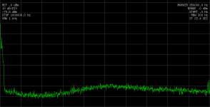
Attached a spectrum dump directly taken at RCA output during playing a song with maximum volume...
As one can see, the output is good filtered - mostly no sampling artifacts in HF range.
BR, Toni
Few people have CD player which directly connects to PA input.
...
Dear Richard,
don't forget the modern stuff: people connecting mini computers e.g. raspberry pi + hifiberry dacplus (with digital volume control included in pcm5122 codec) directly to power amplifiers.
Attached a spectrum dump directly taken at RCA output during playing a song with maximum volume...
As one can see, the output is good filtered - mostly no sampling artifacts in HF range.
BR, Toni
Attachments
Dear Richard,
.
As one can see, the output is good filtered - mostly no sampling artifacts in HF range.
BR, Toni
any HF stuff/junk hiding from you above 20Khz ??
-Richard
Unfiltered! My HP3585A was directly attached using the 1MOhm input.
The sound card was running with this parameters during the screen shot:
8 x oversampling ...
=> that may be the cause for the small peak at cursor position ~ 350kHz.
BR, Toni
The sound card was running with this parameters during the screen shot:
Code:
Setting from alsamixer:
DSP Program [High attenuation with de-emphasis] (see PCM5122 datasheet for details pg. 21 and 83)

From soundcard:
root@raspberrypi:/proc/asound/card0/pcm0p/sub0# cat hw_params
access: RW_INTERLEAVED
format: S24_LE
subformat: STD
channels: 2
rate: 44100 (352800/8)
period_size: 4410
buffer_size: 22050=> that may be the cause for the small peak at cursor position ~ 350kHz.
BR, Toni
Last edited by a moderator:
Hi Richard,
I see a marker at 35,000 Hz, so it looks clean. I'm surprised it does, but maybe the reconstruction filter is part of the chip these days. However, on the earl;y chips like the TDA1541A and other NOS chips used in those designs, I expect a very strong 44.1 KHz signal on those if not filtered by the viscous filters needed there (like 7th and 8th order filters!).
-Chris
20 years ago I was sent a translation of the article by Yoshi Segoshi of the "Non-over, sampling Digital -filter-less DAC Concept" by Ryohei Kusunoki published in MJ magazine between November 1996 and January 1997.
I got the third article - in this Kusunoki speculated that "8x oversampling/digital filter can only cut-off frequencies between 22.05kHz and 330kHz. Everything beyond 330kHz is all coming through untouched, meaning the degree is determined by how " the equipment "reacts to the ingredients beyond 330kHz.''
I have kept a copy but decided to buy a new player instead of building this as a project. The DAC is a TDA1543 feeding a passive output filter involving capacitors and resistors.
- Home
- Amplifiers
- Solid State
- Bob Cordell's Power amplifier book