Since I was on a roll I also did up the DH-200C design as shown in chapters 9 & 14. Bob is also evaluating that one too, like Bob needs more work, especially from me 🙂
Did you manage to layout this design in the same footprint as the Hafler DH-200/220 board? I'm interested to see what you've come up with.
Jeff
Amazon Prime sells 18 AWG "magnet wire" (enamel coating for insulation) at a reasonable price:
BNTECHGO 18 AWG Magnet Wire - Enameled Copper Wire - Enameled Magnet Winding Wire - 1.0 lb - 0.0393" Diameter 1 Spool Coil Red Temperature Rating 155℃ Widely Used for Transformers Inductors: Amazon.com: Industrial & Scientific
BNTECHGO 18 AWG Magnet Wire - Enameled Copper Wire - Enameled Magnet Winding Wire - 1.0 lb - 0.0393" Diameter 1 Spool Coil Red Temperature Rating 155℃ Widely Used for Transformers Inductors: Amazon.com: Industrial & Scientific
yes, see the pic, on the right side, Bob provided me the dimensions of the PC19c original Hafler pcb. I was told that it actually fits the HS ears, except the big cap (1000uF/100V),on the pcb that was originally specified,has to less than 25-30 mm? since on one side, it will interfere with the main ecap. We found a solution to use a smaller sized ecap or you can move the big screw terminal ecaps, I see lots of room 🙂, just a PITA to move.Did you manage to layout this design in the same footprint as the Hafler DH-200/220 board? I'm interested to see what you've come up with.
Was thinking I should do up another OPS to use with DH-220C, for others that do not have a Hafler chassis. A new OPS pcb would be more elegant, easier to assemble, than the original Hafler mech design, as it is a bunch of wires, passives hanging off a terminal strip, to the TO-3 fet devices, that could be better put on a pcb instead. It is mechanical design details. If you look closely at my test devices, I used a spare lateral fet pcb (OPC wire amp) that uses a National LME49830 driver (now obsolete). Used the Alfet dual die devices and the filtering, series gate R's, real simple stuff.
Last edited:
Fig 13.8a LTspice circuit download
An LTspice simulation file of the basic DoubleCrossTM CE output stage can be downloaded here PAK Project – Course Outline - PAK2 devo
A spreadsheet is also available there. It follows Bob's Fig.13.8(a) circuit.
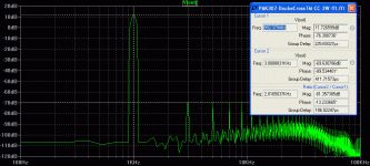
Modifying the LTspice file allows FFT plots. EG changing it to a follower* and with Vin=6V for 2W out for the Class-A region, the THD is around -80dB (see attached). This basic output stage gives an idea of the best that is possible with DoubleCrossTM . (*To change the CE circuit to follower just move the ground on the load to the other side of the load).
Bob reports measuring for just the output stage 0.02% at 5W with a similar bias to what I used. So with 40dB of feedback I estimate the lower limit as 1 ppm at 2W, and 60dB nfb would be 0.1 ppm at 2W.
The big advantage of DoubleCrossTM for me is the wider Class-A region without gm doubling that you normally get when you over-bias in Class-AB. You can get a few watts in Class-A with 230mA total with DoubleCrossTM -- I expect Pass-amp and no-feedback fiends will love it.
I would if I had a schematic/sim or a book I could refer too 🙂 One day hopefullyI hope we see lot's of DoubleCrossTM amplifiers made by members.
An LTspice simulation file of the basic DoubleCrossTM CE output stage can be downloaded here PAK Project – Course Outline - PAK2 devo
A spreadsheet is also available there. It follows Bob's Fig.13.8(a) circuit.
Modifying the LTspice file allows FFT plots. EG changing it to a follower* and with Vin=6V for 2W out for the Class-A region, the THD is around -80dB (see attached). This basic output stage gives an idea of the best that is possible with DoubleCrossTM . (*To change the CE circuit to follower just move the ground on the load to the other side of the load).
Bob reports measuring for just the output stage 0.02% at 5W with a similar bias to what I used. So with 40dB of feedback I estimate the lower limit as 1 ppm at 2W, and 60dB nfb would be 0.1 ppm at 2W.
The big advantage of DoubleCrossTM for me is the wider Class-A region without gm doubling that you normally get when you over-bias in Class-AB. You can get a few watts in Class-A with 230mA total with DoubleCrossTM -- I expect Pass-amp and no-feedback fiends will love it.
Attachments
I am.
Cheers,
Bob
Re: Doublecross
Seems to me that D1 here provides something very similar to the tension bias:
https://www.diyaudio.com/forums/solid-state/125317-easiest-build-class.html#post1546823
The example is low power for headphones but he also mentions using power OP amps for higher power,
not that it matters with regard to the concept.
Hi Bob,
I'm really loving the new edition. Congratulations on a teriffic update to a classic book!
I'd like to offer an observation about the noninverting DC servo shown in Figure 10.8, attached below as Figure 1. My observation is a standard, perhaps hackneyed, religious axiom in DIYaudio: if some is good then more is better! Specifically your opamp U1B implements a first order lowpass filter. But if one is good then two is better (!). Why not use an inverting filter topology like Multiple FeedBack to build a second order lowpass filter? A diagram is shown in the attached Figure 2 below. Expand your browser window to full screen and click the white "X" at lower left to see the images full size.
I wrote the word "Bessel" just to start an argument; I don't think it actually matters whether the filter is Butterworth (zeta=0.5) or Bessel (zeta=0.833) or any other specific "alignment". In my opinion the important details are the cutoff frequency and the order of the filter. Set the cutoff frequency to match the cutoff in Bob Cordell's book, 2nd edition, U1B of Fig 10.8. Set the order of the filter to be two. Done!
What do you think about it?
_
Hi Mark,
Thanks for your very kind words!
Making that inverter-LPF in the second op amp into a 2nd order filter at little expense is a neat idea. My only question is how much difference does it make in the real world after having already put in the first order of extra filtering. Of course, it is also important that putting in an additional order of filtering in the servo feedback loop could cause some unwanted servo loop peaking or instability if it is not done with care. Fortunately, this issue is very amenable to simulation.
Thanks again for your comments.
Cheers,
Bob
I'm looking to build and test the amplifier in Bob's book as a learning exercise. I'm putting together a BOM using Mouser.co.uk. I just have a couple of queries.
In Fig 4.1 Q14 is 2SC3503, Q15 is KSC3503. Mouser stocks the KSC but not the 2SC. Are these essentially the same thing though? Similarly Q13 is 2SA1381 whilst Q16 is KSA1381. Again can I just double up on the KSA?
R26 is a variable 1k resistor, but what does the "(240 typ)" mean? Can this be a 1 turn trim pot, or does it need to be something better?
In Fig 4.2 there is a 1.5uH inductor. Mouser has over 50 1.5uH radial lead inductors. Is there anything else I should be narrowing down the search on, such as max DC current? Would this Bourn 652-RLB0913-1R5K be okay for example?
RLB0913-1R5K Bourns | Mouser United Kingdom
Many thanks
The KSC and 2SC are basically the same part, as are the KSA and 2SA.
For R26, the (240 typ) just indicates that the value is typically set to 240 ohms (e.g., in my prototype - YMMV). In my view, bias pots should always be 10-turn pots (or more).
Amplifier output inductors should always be air core so that there is no magnetic nonlinearity.
Cheers,
Bob
I wish I had the book to refer to the fig 4.1 circuit.
Is it similar to a circuit in the old book that I could refer too?
2SA1381/2SC3503 are the original Sanyo EIAJ part numbers. Fairchild/Onsemi have a dual naming for the second sourced parts, KSA1381/KSC3503 as shown in the data sheets.
240ohm is the nominal set value for an assumed 500 ohm pot. Mark adds that the wiper is shorted to one on the other terminals, cw or ccw to make the variable R.
The 1.5uH inductor is an air core coil, wound using solid enameled magnetic wire. Basically 12 turns, 1" diameter of 18AWG. You do not want a inductor with a ferrite or powered iron core since they saturate and cause distortion.
FYI, I have the amplifier, called "BC-1" in chapter 5 built & operational.
I approached Bob earlier asking if there would be something to build in the new book. The answer was yes and no, there is a complete design but no pcb's available for easy assembly. So, I took it upon myself with Bob's help and encouragement to design a set of pcb's for BC-1. This was done in anticipation that their maybe some interest in book owners wanting to buildup the BC-1 amplifier.
I have sent the pcb's to Bob Cordell for evaluation. Bob graciously offered to review, and now evaluate my design implementation and the build.
Once Bob has given them his approval I will be able to release them for others to use.
I will attach a pic of the set of pcb's in operation. There is a Mouser BOM in a shopping cart in which you will be able to order the parts against. It will be a complete amp with out the chassis and mechanical bits. A 3 board set, a simple & cost effective, rectifier/filter, BC-1 (AFE), BC-1(OPS).
Since I was on a roll I also did up the DH-200C design as shown in chapters 9 & 14. Bob is also evaluating that one too, like Bob needs more work, especially from me 🙂
I must say that Rick has done a beautiful job on the BC-1 and DH220C Boards. I ordered the parts directly from mouser a couple of weeks ago, directly via his BOMs, and have completed stuffing the boards. I am in the very early testing stages.
Thanks very much to Rick.
Cheers,
Bob
Your inductor (12 turns on 1 inch dia) sounds too much for 1.5 uH.
Is this something you have measured?
The inductor is 12 turns on 0.5-inch diameter. It is about 0.5-inch long. I'm pretty sure I measured it, but it was quite some time ago. I'll go back and measure the one on the prototype. It would indeed be nice if the 12 turns on 0.5-inch yields too much inductance, since the inductor would then not need to be as big.
Cheers,
Bob
Vertically mounted air-cores tend to spray their EMI further over the PCB, its better to have
horizontal (or ideally toroidal) arrangement which couple less flux into loops on the PCB.
Good point. I actually did a toroidal 3 uH coil along time ago when I built my Super Gain Clone, but the coil was pretty big. I wound the coil on a pencil and then bent it into a toroid.
I also did some experiments with some compact coils awhile back with a vertical orientation (axis of coil was perpendicular to the PWB surface. I seem to recall they had 2 layers, a smaller diameter, and smaller AWG wire, all to make the coil more compact. Didn't end up doing much with it, though.
Cheers,
Bob
An LTspice simulation file of the basic DoubleCrossTM CE output stage can be downloaded here PAK Project – Course Outline - PAK2 devo
A spreadsheet is also available there. It follows Bob's Fig.13.8(a) circuit.
Modifying the LTspice file allows FFT plots. EG changing it to a follower* and with Vin=6V for 2W out for the Class-A region, the THD is around -80dB (see attached). This basic output stage gives an idea of the best that is possible with DoubleCrossTM . (*To change the CE circuit to follower just move the ground on the load to the other side of the load).
Bob reports measuring for just the output stage 0.02% at 5W with a similar bias to what I used. So with 40dB of feedback I estimate the lower limit as 1 ppm at 2W, and 60dB nfb would be 0.1 ppm at 2W.
The big advantage of DoubleCrossTM for me is the wider Class-A region without gm doubling that you normally get when you over-bias in Class-AB. You can get a few watts in Class-A with 230mA total with DoubleCrossTM -- I expect Pass-amp and no-feedback fiends will love it.
Thanks, Ian. I completely agree - my goal was to allow higher quiescent bias current with a given value of RE without getting into gm doubling; the whole idea being able to have a wider class A region.
A point worth noting is that most push-pull class A amplifiers slip into class AB and gm doubling at high current output. This behavior usually occurs at quite high power levels, and if gm doubling occurs it may not be as intrusive. Nevertheless, one could apply the DoubleCross technique to a nominally class A amplifier to reduce that gm doubling effect.
Cheers,
Bob
The KSC and 2SC are basically the same part, as are the KSA and 2SA.
For R26, the (240 typ) just indicates that the value is typically set to 240 ohms (e.g., in my prototype - YMMV). In my view, bias pots should always be 10-turn pots (or more).
Amplifier output inductors should always be air core so that there is no magnetic nonlinearity.
Cheers,
Bob
Thanks Bob, much appreciated. I best get on and order my parts before I lose momentum!
Bought you latest book, Bob.
Thanks John! I hope you enjoy it.
Cheers,
Bob
Making that inverter-LPF in the second op amp into a 2nd order filter at little expense is a neat idea. My only question is how much difference does it make in the real world after having already put in the first order of extra filtering.
Would the steeper slope aid in reducing settling time? I've noticed on Tom C's Modulus 86 circuit description page, he states: "An OPA2277 precision op-amp is used as a high-end DC servo with third order filtering for an ultra-low output DC offset and fast settling time". It's not clear to me if the 3rd order filter is part of the mechanics that reduce settling time.
If this is true, it seems this would be a benefit for topologies the require a DC servo to function (singleton input stage for example).
Settling time depends on the time domain performance of the filter used, not simply the order, no Chebyshev is going to settle fast due to lots of ringing, Bessel would by pretty good. Gaussian would be best, but can't be realized exactly.
Methinks "settling time" may refer to the entire control loop, which comprises the audio power amplifier's forward path, the first stage of the DC servo (inverting integrator), and the proposed second stage (inverting N-th order lowpass active filter with alignment X).
Apply a unit impulse and watch it settle (or watch it oscillate)
Apply a unit impulse and watch it settle (or watch it oscillate)
- Home
- Amplifiers
- Solid State
- Bob Cordell's Power amplifier book