Hello
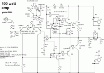
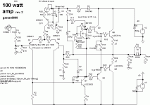
Here is a schematic of an amp that I've made for a friend a year and a half ago, I prefer simple circuits since more complicate one don't allways sound better.
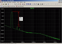
I've re-simulate it (but this time using LTspice) at 100 watt, it's a Linn topology with ccs and LTP but no CM. it use a boot strap and no CCS for the vas, and a phase lead capacitor so the miller capacitor (lag compensation) can be lower with the same stability. It look good at sim thd and should sound very good.
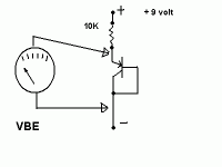
It sound better if you matched the two LTP input transistors for HFE and VBE.
You adjust the offset using R7, for minimum dc output. Bias are adjust with R19 at 60 ma.
You need to use a low cob and fast speed for Q7 the vas transistor, at least 120 mhz with a cob lower than 10 pF.
The miller cap (lag comp) C12 and the phase lead cap C13, should be silver mica.
If you use faster driver transistors, you can lower the value of the suckout capacitor C11 to arround 175 nF.
All capacitor should be rated at 100 volt.
For those who would suggest a CCS for the vas, I founded the boot stap to be better sounding, so I use boot strap.
This amp will sound very musical with a very good sound-stage.
Btw, R2 are no more to adjust the offset, so forget the text saying that R2 are for offset adjusting. I forget to delete it and I can't modified the posted images.
I include images of the circuit, the thd spectrum and also a very simple vbe test for the matching the two LTP input transistors.
I thank Hugh Dean for his good help and teaching since few years, without him I would never done this amp.
Bye
Gaetan
Attachments
Last edited:
Congratulations, Gaetan!!
Nice amp..... you might need a bit more adjustment on R7 to achieve offset control. I'd suggest making R30 820R, and R7, the pot, 200R.
When output offset is adjusted to within +/-20mV, the two arms of the LTP should be in almost perfect balance if the matching of the diff pair is good.
This does mean matching beta, of course, but also the Vbe with 1mA flowing through the device.
Ciao,
Hugh
Congratulations, Gaetan!!
Nice amp..... you might need a bit more adjustment on R7 to achieve offset control. I'd suggest making R30 820R, and R7, the pot, 200R.
When output offset is adjusted to within +/-20mV, the two arms of the LTP should be in almost perfect balance if the matching of the diff pair is good.
This does mean matching beta, of course, but also the Vbe with 1mA flowing through the device.
Ciao,
Hugh
Hello Hugh
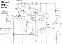
R7 and R19 value was for the sim testing, but R7 trimpot value should be 200 ohm, and R19 trimpot value should be 500 ohm and forgot to bring them back.
Sorry but I have problems to see details on my computer screen, so I forgot details quite often.
I include a rev. 2 of my circuit with right trimpots values.
Thank
Bye
Gaetan
Attachments
Last edited:
Hi
I've done the rev 2 schematic and used 10p for the c13 cap.
This amp sound delightful, Diana Krall and Norah Jones sound so good, even orchestral music are a bliss with this amp.
Thumb up for you sir
Btw, his there anyone who know a simple DC detect circuit ?
Thanx
Paul
I've done the rev 2 schematic and used 10p for the c13 cap.
This amp sound delightful, Diana Krall and Norah Jones sound so good, even orchestral music are a bliss with this amp.
Thumb up for you sir
Btw, his there anyone who know a simple DC detect circuit ?
Thanx
Paul
Last edited:
Hello
Here is a rev.1 of the circuit of my amp, I've deleted the the text saying that R2 are for offset adjusting.
You adjust the offset using R7
Bye
Gaetan
R7 is to set current through input differential pair. Adjusting offset this way (it will make some adjustment, because diff pair transistors are not ideally matched) is more or less pointless.
djk;2707875..........Adjusting the LTP current changes the current in the Vas said:is this back to front?
The Vas Vbe sets a voltage across the collector load on one side of the LTP.
This voltage sets a current and that collector current then passes down through one half of the LTP.
The other half of the LTP gets sunk/fed with the remaining tail current that is set up in the tail resistor/CCS.
Now the two LTP resistors measure what is happening at their two respective bases and adjust the output such that the fedback voltage at -IN matches the +IN voltage +- the errors in Vbe and other errors across the LTP. It's the LTP that generates the output offset.
If both halves of the LTP have identical transistors and identical currents and identical voltages and identical temperatures then they try to make +IN = -IN (just like an opamp). Change any one or more of those identical conditions and you force the LTP to generate an error voltage.
Has anyone got/made the pcb artwork for this amp?
Hello
It's a fairly simple amp to buid, myself I've used aerial copper wires to build it.
Just be carefull NOT to put the input and vas transistors close to the output transistors or to the rails, and you need to use a star ground.
Don't use the BD139 to replace the KSC3503 in the vas, the BD139 are slow and have a quite high COB for a vas, so it would reduce the slew-rate and the quality of the sound. So if you don't have the KSC3503 or 2SC3503 use a transistor with a minimum FT of 125 mhz and a COB lower than 12 pf.
Bye
Gaetan
Last edited:
can this be a help to you?
check for possible mistakes.this pcb is not yet tested.
When the PCB will be placed?
thanks
check for possible mistakes.this pcb is not yet tested.
Attachments
Hello
Try to matched the two LTP input transistors for HFE and VBE.
For the offset you may need to adjust the value of R30, try the 930 ohm value, if the offset still higher than 50 mv wen you adjust the R7 trimpot, you can reduce R30 to 700 or 500 ohm.
After adjusting the offset, you can do a fine adjustement of the LTP transistors balance by measuring the voltage drop across R5 and R10 to get the same voltage by adjusting the R7 trimpot.
For those using drowranger pcb, do a very carefull check to see that you will not have any solders bridges between pad and track or between track.
Be sure to use a big enough heatsinks for the vbe, drivers and output transistors.
Thank drowranger for your nice pcb works, if you want to put a name you can name it "Gaetan amp".
Bye
Gaétan
Last edited:
- Status
- This old topic is closed. If you want to reopen this topic, contact a moderator using the "Report Post" button.
- Home
- Amplifiers
- Solid State
- My 100 watt amp
