Hello
Here is the Bill of Materials according to my schematic:
Ref. Description
C1 -- -- capacitor, 100µF, 63V
C2 -- -- capacitor, 100F, 63V
C3 -- -- capacitor, 1nF
C4 -- -- capacitor, 1µF, 50V
C6 -- -- capacitor, 500µF, 63V
C7 -- -- capacitor, 500µF, 63V
C8 -- -- capacitor, 100nF
C9 -- -- capacitor, 200µF, 50V
C10 -- -- capacitor, 47µF, 50V
C11 -- -- capacitor, 220nF, 50V
C12 -- -- capacitor, 30pF, 50V
C13 -- -- capacitor, 6pF, 50V
D2 -- -- 1N4148 diode
D3 -- -- QTLP690C diode
L1 -- -- inductor, 1µH
Q1 -- -- 2N5401 bipolar transistor
Q2 -- -- BD139 bipolar transistor
Q3 -- -- mje15032 bipolar transistor
Q4 -- -- 2N5401 bipolar transistor
Q6 -- -- mjl0281a bipolar transistor
Q7 -- -- KSC3503 bipolar transistor
Q8 -- -- mje15033 bipolar transistor
Q9 -- -- mjl0302a bipolar transistor
Q11 -- -- 2N5401 bipolar transistor
R1 -- -- resistor, 100m, 1%, 0.1W
R2 -- -- resistor, 500
R3 -- -- resistor, 2K, 1%, 0.1W
R4 -- -- resistor, 10, 1%, 0.1W
R5 -- -- resistor, 10, 1%, 0.1W
R6 -- -- resistor, 3K
R7 -- -- resistor, 1, 1%, 0.1W
R8 -- -- resistor, 2.5K, 1%, 0.1W
R9 -- -- resistor, 100, 1%, 0.1W
R10 -- -- resistor, 10, 1%, 0.1W
R11 -- -- resistor, 4K, 1%, 0.1W
R13 -- -- resistor, 100, 1%, 0.1W
R15 -- -- resistor, 10, 1%, 0.1W
R16 -- -- resistor, 470m
R17 -- -- resistor, 200, 1%, 0.1W
R19 -- -- resistor, 245, 1%, 0.1W
R20 -- -- resistor, 100, 1%, 0.1W
R21 -- -- resistor, 50K, 1%, 0.1W
R22 -- -- resistor, 100, 1%, 0.1W
R23 -- -- resistor, 10, 1%, 0.1W
R24 -- -- resistor, 470m, 1%, 0.1W
R25 -- -- resistor, 1.5K, 1%, 0.1W
R26 -- -- resistor, 10, 1%, 0.1W
R27 -- -- Loudspeaker
R30 -- -- resistor, 900, 1%, 0.1W
R32 -- -- resistor, 5K, 1%, 0.1W
R33 -- -- resistor, 5K, 1%, 0.1W
R34 -- -- resistor, 47K, 1%, 0.1W
R35 -- -- resistor, 200, 1%, 0.1W
two small heatsinks for Q3 and Q8
one big heat sink for Q6 and Q9
Bye
Gaetan
change name of Q5 TO Q7
Thanks,
joel
Hello drowranger
I've just done a fast look at your pcb and your PDF file of my schematic, the vas transistor (KSC3503) should be marked Q7.
Thank
Bye
Gaetan
Thanks,
joel
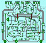
Attachments
Hello
Joel:
Very nice work. Give us your listening impressions wen you will built it, it take about 20 to 50 hours to the electro cap to settle, so it take some times of burn-in to an amp to sound at it's full potential.
For all others:
The reason to matched the two LTP input transistors for HFE and VBE and also to balance those two transistors are for a better linearity and lower distortions, that's give a sound with a better resolution and sound-stage.
Bye
Gaetan
Last edited:
Hello gaetan 8888!
Where is the diode D1?
Why diodes D2=1N4148, instead 1N4007 ?
Why no parallel capacitor 100nF with the C1?
Why no parallel capacitor 100nF with the C9?
What is the replacement for the Q7 (KSC3503) ?
LED D3 should be green or red?
I think to be green!
R9 think should be the 0,5W for power supply Us=+/-36Vdc!
R24 -- -- resistor, 470m, 1%, 0.1W ??? - check?!
thanks and cheers
Last edited:
Hello gaetan 8888!
Where is the diode D1?
Why diodes D2=1N4148, instead 1N4007 ?
Why no parallel capacitor 100nF with the C1?
Why no parallel capacitor 100nF with the C9?
What is the replacement for the Q7 (KSC3503) ?
LED D3 should be green or red?
I think to be green!
R9 think should be the 0,5W for power supply Us=+/-36Vdc!
R24 -- -- resistor, 470m, 1%, 0.1W ??? - check?!
thanks and cheers
Hello
Few years ago, I've done all tests of my hand draw schematic using LtSpice simulator, so that software assigned a number to all parts and I've never change them.
And there was no need in that LtSpice simulation to put any watts values on the resistors, so LtSpice arbitrary put .1w on most resistors in the BOM file, I've just forgot to check them in the file (I will correct that)
That's why that there is no diode D1.
1N4148 are just faster, but you can use 1N4007.
To do it simple I've not put a parallel capacitor 100nF with the C1 and C9, but you can add them.
To replace Q7 (KSC3503), use any NPN transistor with a minimum FT of 100 or 125 mhz and a COB lower than 8 pf.
LED D3 should be green, NO high power led.
I will check the Bom and repost it.
Thank for cheking it.
Bye
Gaetan
Last edited:
Hello
Here is the corrected version of the Bill of Materials
Bye
Gaetan
Ref. Mfg. Part No. Description
C1 -- -- capacitor, 100µF, 63V
C2 -- -- capacitor, 100F, 63V
C3 -- -- capacitor, 1nF
C4 -- -- capacitor, 1µF, 50V
C6 -- -- capacitor, 500µF, 63V
C7 -- -- capacitor, 500µF, 63V
C8 -- -- capacitor, 100nF
C9 -- -- capacitor, 200µF, 50V
C10 -- -- capacitor, 47µF, 50V
C11 -- -- capacitor, 220nF, 50V
C12 -- -- capacitor, 30pF, 50V
C13 -- -- capacitor, 6pF, 50V
D2 -- -- 1N4148 diode
D3 -- -- QTLP690C diode
L1 -- -- inductor, 1µH
Q1 -- -- 2N5401 bipolar transistor
Q2 -- -- BD139 bipolar transistor
Q3 -- -- mje15032 bipolar transistor
Q4 -- -- 2N5401 bipolar transistor
Q6 -- -- mjl0281a bipolar transistor
Q7 -- -- KSC3503 or 2SC3503 bipolar transistor
Q8 -- -- mje15033 bipolar transistor
Q9 -- -- mjl0302a bipolar transistor
Q11 -- -- 2N5401 bipolar transistor
R1 -- -- resistor, 100m, 5%, 0.25W
R2 -- -- resistor, 500
R3 -- -- resistor, 2K, 5%, 0.25W
R4 -- -- resistor, 10, 5%, 0.25W
R5 -- -- resistor, 10, 5%, 0.25W
R6 -- -- resistor, 3K, 5%, 0.25W
R7 -- -- resistor, 1, 5%, 0.25W
R8 -- -- resistor, 2.5K, 5%, 0.25W
R9 -- -- resistor, 100, 5%, 0.5W
R10 -- -- resistor, 10, 5%, 0.25W
R11 -- -- resistor, 4K, 5%, 0.25W
R13 -- -- resistor, 100, 5%, 0.25W
R15 -- -- resistor, 10, 5%, 0.25W
R16 -- -- resistor, 470m, 5%, 5W
R17 -- -- resistor, 200, 5%, 0.25W
R19 -- -- resistor, 245, 5%, 0.25W
R20 -- -- resistor, 100, 5%, 0.25W
R21 -- -- resistor, 50K, 5%, 0.25W
R22 -- -- resistor, 100, 5%, 0.25W
R23 -- -- resistor, 10, 5%, 0.25W
R24 -- -- resistor, 470m, 5%, 5W
R25 -- -- resistor, 1.5K, 5%, 0.25W
R26 -- -- resistor, 10, 5%, 0.25W
R27 -- -- 8 ohm Loudspeaker
R30 -- -- resistor, 900, 5%, 0.25W
R32 -- -- resistor, 5K, 5%, 0.25W
R33 -- -- resistor, 5K, 5%, 0.25W
R34 -- -- resistor, 47K, 5%, 0.25W
R35 -- -- resistor, 200, 5%, 0.25W
two small heatsinks for Q3 and Q8
one big heat sink for Q6 and Q9
Hello
No, BC639 do have arround 50mhz for the Ft, that's too slow for Q7.
2N5551, with a heat-sink, can be use for Q7
Yes; 470m, 5%, 5W = 0.47ohm / 5% / 5W
D3 - - QTLP690C diodes are the part number chosen for the test, but any standard green led will do, but NO high power led.
Remember to adjust the bias at 70ma. (R19 trimpot)
L1 should be a air coil.
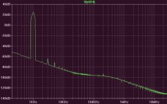
I include the distortions spectrum of my amp, it have arround -90 db of distortions, that is .005% of distortions at 50 watts output in 8 ohm.
If you want to use my amp with a 4 ohm load you need a BIG heat-sink, because a 4 ohm loudspeaker can go lower than 4 ohm.
Bye
Gaetan
No, BC639 do have arround 50mhz for the Ft, that's too slow for Q7.
2N5551, with a heat-sink, can be use for Q7
Yes; 470m, 5%, 5W = 0.47ohm / 5% / 5W
D3 - - QTLP690C diodes are the part number chosen for the test, but any standard green led will do, but NO high power led.
Remember to adjust the bias at 70ma. (R19 trimpot)
L1 should be a air coil.
I include the distortions spectrum of my amp, it have arround -90 db of distortions, that is .005% of distortions at 50 watts output in 8 ohm.
If you want to use my amp with a 4 ohm load you need a BIG heat-sink, because a 4 ohm loudspeaker can go lower than 4 ohm.
Bye
Gaetan
Attachments
Last edited:


Hi
Check datasheet for BC639 (fT = 200MHz typ.)?!
Regards
Hello
In my Towers International transistor selector book third edition, page 163,
BC639 the fT = 50MHz this one are made by Telefunken.
Maby a typo error in the book, I will check in the Net.
Bye
Gaetan
Last edited:
Signs BC639 transistor is OK?!Hello
The fT spec of the BC639 change from a manuacture to another:
Fairchild Semi: min;50mhz - typical;100mhz
NPX: min;100mhz - typical;180mhz
Onsemi: typical;200mhz
Bye
Gaetan

Cheers
Last edited:
Signs BC639 transistor is OK?!
Cheers
Hello
Telefunken and Fairchild are borderline slow.
NPX and Onsemi are good, so take those brand of BC639 and use a heat-sink because it is a bit low wattage transistor.
So, if you allready have some BC639, check who's manuacture them.
Bye
Gaetan
Last edited:
- Status
- This old topic is closed. If you want to reopen this topic, contact a moderator using the "Report Post" button.
- Home
- Amplifiers
- Solid State
- My 100 watt amp