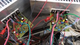
Finally finished my FX100 Stereo pair. Still a lot of work to do,as i would like to put this Pair in a case. Still have to finish up FX PWR Supply & get 42V Transfmr.
Running 20ma per device @+-56V. Does that sound reasonable to everyone.?
Rick
Hi Rick,
What I found was, the amp plays better with higher bias. >=80mA per pair is the sweet spot . I had set mine at about 90mA. Plays sweet and is very quiet.
reg
Prasi
Not quite the way to understand the bias current in the circuit.....So that is 40MA per Device = 160MA total @56V = 8.96 watts at idle.?
Each complementary pair of output transistors (Q11/Q9 and Q12/Q10) is connected in series. 80mA current would flow from the + rail through the upper transistor, then to the lower transistor and the - rail. Each transistor in the pair effectively receives the same 80 mA current. The second pair in parallel with these, is doing the same and so by current sharing, doubles the total bias current to 160mA.
Generally, 100 mA per pair is considered minimum for good mosfet sound. There is no maximum, right through to full class A operation, if massively beefed up to suit.
I am not sure you have arrived at the correct answer.OK. Thank you Prasi, i will give that a try.
So that is 40MA per Device = 160MA total @56V = 8.96 watts at idle.?
Consider just one device.
What is the current through it in Amperes?
What is the voltage across it in Volts?
Multiply the device current by the device voltage and you arrive at the device dissipation. (ignoring base current, a mosFET has virtually no gate current so this part can be ignored).
How many output devices are there?
Multiply device dissipation by device number and you arrive at the heatsink dissipation.
eg.
one device has Vds=56Vdc and 0r22 source resistor has a volts drop of 12mVdc.
Id = 0.012Vdc/0.22ohms = 0.0545Adc
Pdiss = 56Vdc*0.0545Adc = 3.05W
A 2pair output stage has 4 devices
Heat transferred to heatsink is 3.05W*4 = 12.2W
Thank You for that Explanation. That explains the heat i am feeling at idle with 30ma per device.
Id =.030/.22 = .14Adc
Pdiss =56Vdc*.14Adc = 7.64W
7.64*4=30.55W
Rick
Rick, this is not what andrew explained. you have considered current(30mA), he has considered voltage drop (12mVDC) across resistor. I=V/R
Last edited:
I dont understand why the servo feedback signal is injected on the non inversing input ( with the input signal )
Why they dont inverse the 2 input of the integrator .... and then inject the correction signal on the other side of the differential .... ( at the node betwen C8 & R14 in your schematic ) C8 would be used to filter a fair part of the noise .... and less noise would be injected in the amplifier.... ?
Why they dont inverse the 2 input of the integrator .... and then inject the correction signal on the other side of the differential .... ( at the node betwen C8 & R14 in your schematic ) C8 would be used to filter a fair part of the noise .... and less noise would be injected in the amplifier.... ?
MegaVolts..... i ment MV,
now you really are confused !getting myself all crossed up with the verbage. I am measuring using the MV scale.
Sorry, i ment MV, getting myself all crossed up with the verbage. I am measuring using the MV scale.
30mV=136mA , nice bias... must be sounding nice... that why it(heatsink) must b getting heated up too!
Last edited:
MegaVoltsnow you really are confused !
c'mon Andrew
") , sometimes you need to forget typing mistakes and concentrate on intended information (hopefully)!
, sometimes you need to forget typing mistakes and concentrate on intended information (hopefully)!
I dont understand why the servo feedback signal is injected on the non inversing input ( with the input signal )
Why they dont inverse the 2 input of the integrator .... and then inject the correction signal on the other side of the differential .... ( at the node betwen C8 & R14 in your schematic ) C8 would be used to filter a fair part of the noise .... and less noise would be injected in the amplifier.... ?
I would be glad (I am sure Mr. Miles too), if you could post a sch with sim results and show us the improved design...
. really! i would love to build it.I would be glad (I am sure Mr. Miles too), if you could post a sch with sim results and show us the improved design...
with 3 pairs at 70 VDC supply!
So many Rules.....So little time. So what is the math to do the mv to ma conversion or vise versa.
Ohm's Law
Use this.So many Rules.....So little time. So what is the math to do the mv to ma conversion or vise versa.
Ohms Law Calculator
- Status
- This old topic is closed. If you want to reopen this topic, contact a moderator using the "Report Post" button.
- Home
- Amplifiers
- Solid State
- DC Servo MOSFET Amplifier