URLthis guy is currently building it and a schematic is provided on his site.
403 | Forbidden | University of Southampton
If you are interested I can post some pics of mine...
403 | Forbidden | University of Southampton
is death in the meantime.
but still available by webarchive:
https://web.archive.org/web/20010115132000/http://www.soton.ac.uk/~apm3/diyaudio/Poweramp.html
https://web.archive.org/web/20010214073044/http:
The schematics from there I have save here:
Attachments
URL
403 | Forbidden | University of Southampton
is death in the meantime.
but still available by webarchive:
High-speed 100W amplifier design
HTTP Archive
The schematics from there I have save here:
Yes, sorry about that - my account at the University seems to have expired, though I still have all the files. I gave Bill all the relevant issues of EW when I passed over my build of the amps, so hopefully he should be able to scan them.
Alex
Hi Bill,I have some updates from Giovanni to post, will try and get those up today.
Thanks - will you copy the e-mail text too (not the to and from ) ???
Or do you want me to do that ?
Regards,
Shadders.
OK This will be in around 3 parts as I pull things together so the flow makes sense. A bit of history behind this. Richard wanted to trace the full history of Giovannis work into fast amplifiers with the goal of building his own. Giovanni supplied a complete set of all his historical articles. I don't want to post them here in case of copyright issues but if anyone wants them then please let me know. In the following posts Q and A between Richard and Giovanni are marked with initials R and G.
I should note in this I am an interested bystander as I have 4 channels of the ultrafast amp in two stereo units. One of which died fairly spectacularly and needs a complete rebuilt, the other of which needs a good tune up and a debug of the protection circuit which trips whenever I crank things up. But other than that I am very happy with the stochino design as it gets out of the way and plays music.
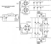
A key point of the discussion was on running off higher rails than the original design. Richard has suitable transformers for +/65v rails
R:I do have some 1kVA transformers - and the power supply design is multiple rail - input/driver stage and output stage. For convenience i will use a single power supply (+/-65volts), which i assume will only restrict the potential voltage rail swings.
G: As you can see in the attached report, I recommend the use of a single dual supply voltage (50V to 60V is ok), but 65V is probably too high and some devices could be forced to work outside their SOA. If you are ready to accept the risk….
Attached is the report, which covers enhancements for improved reliability including removing the seperate supply for the driver stage. These mods were designed to be done on the original board
I should note in this I am an interested bystander as I have 4 channels of the ultrafast amp in two stereo units. One of which died fairly spectacularly and needs a complete rebuilt, the other of which needs a good tune up and a debug of the protection circuit which trips whenever I crank things up. But other than that I am very happy with the stochino design as it gets out of the way and plays music.
A key point of the discussion was on running off higher rails than the original design. Richard has suitable transformers for +/65v rails
R:I do have some 1kVA transformers - and the power supply design is multiple rail - input/driver stage and output stage. For convenience i will use a single power supply (+/-65volts), which i assume will only restrict the potential voltage rail swings.
G: As you can see in the attached report, I recommend the use of a single dual supply voltage (50V to 60V is ok), but 65V is probably too high and some devices could be forced to work outside their SOA. If you are ready to accept the risk….
Attached is the report, which covers enhancements for improved reliability including removing the seperate supply for the driver stage. These mods were designed to be done on the original board
Attachments
Part 2:
G:I’ve been reflecting for a while on your idea to power your ultra-fast amplifiers by +/-65V.
With the attached report, I want to provide you with a few recommendations that I’m sure, when applied, will mitigate the risk of fault of the most critical devices when operating with supply voltages higher than the specified +/- 55V. The penalty to be paid in terms of speed, due to the increased equivalent input capacitance of the driver, is minimal and worth to be accepted.
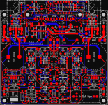
The impact on to the 1998 design is higher than with the solution I proposed with my previous report, yet I think this will not represent a major problem for you Richard, since, as far as I understand, you need to design the PCB for your own amplifiers.
However, the suggested changes can be beneficial also for the lower supply voltages of the original design, and therefore I want to invite you Bill to examine the possibility to find a way (unfortunately hard!!) to incorporate these upgrades into your ultra-fast amplifiers.
G:I’ve been reflecting for a while on your idea to power your ultra-fast amplifiers by +/-65V.
With the attached report, I want to provide you with a few recommendations that I’m sure, when applied, will mitigate the risk of fault of the most critical devices when operating with supply voltages higher than the specified +/- 55V. The penalty to be paid in terms of speed, due to the increased equivalent input capacitance of the driver, is minimal and worth to be accepted.
The impact on to the 1998 design is higher than with the solution I proposed with my previous report, yet I think this will not represent a major problem for you Richard, since, as far as I understand, you need to design the PCB for your own amplifiers.
However, the suggested changes can be beneficial also for the lower supply voltages of the original design, and therefore I want to invite you Bill to examine the possibility to find a way (unfortunately hard!!) to incorporate these upgrades into your ultra-fast amplifiers.
Attachments
Thanks for posting that, Bill. I don't have an active interest in Giovanni's amplifiers these days, but since I spent a lot of time studying the circuit, then building my four channels and finally working out how to apply the mods found earlier on this thread, I do enjoy reading about the design.
I'm surprised Giovanni hasn't taken on board the idea of using higher-Hfe input transistors to reduce the DC offset.
Alex
I'm surprised Giovanni hasn't taken on board the idea of using higher-Hfe input transistors to reduce the DC offset.
Alex
Hi
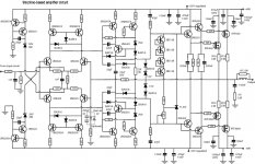
Fast is not as important as low-THD. The THD20 on this amp is entirely unimpressive and THD1 should be much better.
The low-value DC block for the feedback loop is antiquated and contributes to the high-THD.
The gate-spread resistors are too high at 1k3, since these are needed to discharge the gate capacitance of the output mosfets and should be a low value. This is really no different than the base-to-base resistor in an EF2. Attention t this would likely make the amp faster stll.
Hi
The low-value DC block for the feedback loop is antiquated and contributes to the high-THD.
That was actually my main conceptual objection to the design, and was the reason I set out down the road of trying to reduce the input offset to allow me to remove those electrolytic caps altogether. As Bill has found, I never quite got there...
Alex
- Status
- This old topic is closed. If you want to reopen this topic, contact a moderator using the "Report Post" button.
- Home
- Amplifiers
- Solid State
- Giovanni Stochino's ultra fast amp