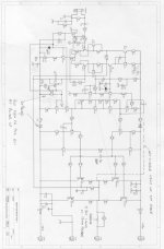
Hi Folks, first post from a relative newbie and former lurker, so here goes...hope you can read the circuit....its long, bear with me.
I am actually a switch mode PSU designer who moved into analogue and mixed signal semiconductor sales... it pays more!My background is Linear Tech, Burr Brown, Unitrode, TI but I have always had a hobby of audio dating back to when I was 11 years old...a long time ago now. Now I am selling motors..more on that another day.
I first experimented with nested feedback by putting a 400W MOSFET amp inside the feedback loop of a OPA627. Fixes the DC drift just great...and actually works quite well. Why...the sales director wanted 'more bass'. I reckon he just needed to clean out his ears...
But it got me interested in nested feedback, and I read the Cherry papers. And wished I could remember more of the stuff I learned at college.....that's what sales does to you.
The original objective was, using the Cherry paper (with his permission for hobbist use incidentally), duplicate his results and make a judgement as to the subjective audio quality.
As time went on the project slowly mutated into a 'make it as best you can' then apply NDFL feedback.
The input stage was elaborated to a CFP type in an attempt to achieve best linearity with the minimum additional complication.
The Rush stage was retained but with the inclusion of R21 to limit the maximum stage gain to something sensible...I am a pom after all so good to have a UK circuit in a Monash Univ. paper!
The VAS transistor was chosen as a BF469, to preserve as much HF performance as possible, rather than use a MJE. I appreciate other much better (and easier to obtain) transistors exist now.
Likewise the current source for the VAS stage was elaborated to a cascode. Later this was found very handy as it was modified to dethump the amp at turn on and diodes were added to the supply rails to prevent positive feedback thumping the amp at turn off.
The output stage was eleaborated into a CFP driver with common emitter output. The object here was to present minimal loading to the VAS, maxmimised voltage swing and allow multiple pairs of output devices to be driven, if a high power version was required.
The prototype used Rod Elliots P03A as the driver...thanks Rod!
The output and driver transistors are the newish On Semi MJE15035 and 36 with MJL4XXX outputs.
The thermal tracking is split into two, one Vbe multiplier tracking the driver drift, the other tracking only the output temperature mounted smack on the face of the output transistor. This appears to work very well.
In the Cherry paper he suggests that including the output stage withn the CDOM loop is acceptable, it is certainly not using this more elaborate and possibly slower output stage, hence the position of C9 is conventional except that it is now part of a nested system.
The choice of transistors is not totally trivial in this design BTW, quite a lot of work was undertaken to prove the CFP stages were stable.
What does it sound like...well I think pretty good, no transistor 'edge' and very good resolution. It has powerful
but uncoloured bass too.
BTW some years ago I built the Self amps and verified his results..yes he's right THD+N circa <0.0005 in a 80KHz BW (APS1 noise floor stuff) but the amps sound diabolical on music, still have the pcbs if anyone interested. For anyone trying this, wiring up the amps and the test equipment is more critical than the choice of transistors...back to the Cherry amp..
Spice analysis (thanks LTC, great free tool!) shows the overall loop gain to be very similar to an amplifier with 2 pole CDOM feedback, very high gain at low frequency, followed by a 2 pole roll off reducing to a single pole at unity. But this is achieved in a more controlled fashion, so I suspect, but cannot prove, lower overall distortion.
What do you guys out there in DIY land think? 😀 or
And thanks to Hugh Dean for tea and sympathy...sympathy for trying to build this thing in the first place!
Attachments
You got a pretty good mentor there, Hugh's amps seem great to me 🙂
It is well worth looking at Fairchild's range of transistors. They have some excellent parts - in fact they cover power amps from pretty much small signal to power output now!
KSC1845/KSA992 - nice small signal parts
KSC3503/KSA1381 - make excellent VAS and predrivers
KSC2690/KSA1220 - similar to above but more current, good for small stage drivers/headphone outputs
FJL4215/FJL4315 - second sourced 2SA1943/2SC5200 of excellent quality, also available in TO3P and TO220 versions.
Best of all, you can order small quantities direct, so guaranteed no fakes 🙂
The drawing's a bit too small to make anything out I'm afraid. Better to use a PNG image with a low number of colours.
Hi,
I kind of found Hugh by accident and we have had lots of dicussions about various aspects of audio design. I want Hugh to listen to the Cherry circuit, and hoping that might happen soon
Yes the transistors are not the best although the output devices and the CFP driver seem to be well suited and stable.
I'll have another go with the schematic!
Thanks!
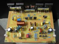
Cherry amp photo
Here is a photo of the prototype. Hope this is better than the circuit..
The little pile of bits is the de thump circuit...now hidden underneath.
The pcb was my first Protel effort, and I made the mistake of using the library TO92 outline, so the pads are impossibly small. A colleague etched the pcb from a ink jet tranparency master, and kindly drilled it for me. The layout was done specifically to be single sided, there are 3 links, all short.
Its all a real 'garage' job so not perhaps as professional looking as I would like.
Attachments
this is very interesting. NDFL is still the best way for all kinds of not hard running amps (i. e. ClassAB) - so I think. Can you upload your simulation results? For example see my pdf versions about this one
http://www.diyaudio.com/forums/showthread.php?s=&threadid=147811
http://www.diyaudio.com/forums/showthread.php?s=&threadid=147745
http://www.diyaudio.com/forums/showthread.php?s=&threadid=147811
http://www.diyaudio.com/forums/showthread.php?s=&threadid=147745
Hi,
Yes I'll try to post the plots. Might have to remake the Spice model as things have moved on a bit since I built the amp and the orginal correct model has become a little ...ahem...corrupt!
Should have saved it before I started changing it...!
Yes I'll try to post the plots. Might have to remake the Spice model as things have moved on a bit since I built the amp and the orginal correct model has become a little ...ahem...corrupt!
Should have saved it before I started changing it...!
A sequel to all of this, rather late yet again...as so common with low distortion amplifiers IMO, this thing does not sound very good, flat as a pancake sound stage etc etc. Hugh agrees, so I am looking at other possibilities. Its a shame because the thing is actually stable, very low noise, etc etc, but lacks that certain something.....bet you have heard all this before many times.
A sequel to all of this, rather late yet again...as so common with low distortion amplifiers IMO, this thing does not sound very good, flat as a pancake sound stage etc etc. Hugh agrees, so I am looking at other possibilities. Its a shame because the thing is actually stable, very low noise, etc etc, but lacks that certain something.....bet you have heard all this before many times.
Unfortunately, you don't mention a little about the boundary conditions like e. g. power supply, the used power capacity, the loudspeakers and the load impedance.
My experience is by soundcheck of power amplifiers, that the cause in the case of a bad sound are mostly due to hugh errors regarded power supplies, GND management and similar thinks.
For the perception of differences that are clearly due to the circuit topology I need perfect conditions and identical conditions concerning the environmental stuff (not very easy to realize).
.............this thing does not sound very good, flat as a pancake sound stage etc etc..........
This sounds like bad or too small supply capacitors, too small transformer, too low load impedance and/or bad GND/mass management.
in the no longer available German magazine "ELRAD" (from the same publisher of the popular computer magazine "Ct") this topology has been described in detail (February/March 1984 and an update to the old schematic in September 1988 and the ELRAD special edition number 2)
you can order copies there:
heise online - Home
here an ebay auction about the "ELRAD 2" special edition
http://cgi.ebay.com.au/ws/eBayISAPI...49518&_sacat=See-All-Categories&_fvi=1&_rdc=1
Elrad,Band:2*Magazin für Elektronik*Bauanleitungen*TOP1 bei eBay.de: Computer Technik (endet 05.02.10 11:10:49 MEZ)
here some additional advices about NDFL (go to page 51 post #505 and #506)
http://www.diyaudio.com/forums/software-tools/101810-spice-simulation.html
and
http://www.diyaudio.com/forums/soli...d-feedback-how-realy-works-some-examples.html
Attachments
Last edited:
Welcome to the forum, Jon - long may you be here!
Not sure about tief's 'hugh errors'. Is this something I should be concerned about in my designs? Must check my ground regime....... (or speak to my Mother)
Hugh
Not sure about tief's 'hugh errors'. Is this something I should be concerned about in my designs? Must check my ground regime....... (or speak to my Mother)
Hugh
What does it sound like...well I think pretty good, no transistor 'edge' and very good resolution. It has powerful but uncoloured bass too.
😕...IMO, this thing does not sound very good, flat as a pancake sound stage etc etc.
Has something changed or are you just being more critical now?
btw I seem to remember that Dr Cherry's amp (published in ETI in May 1983) had a rather diabolical protection circuit that looked like it might cripple performance into real speaker loads.
The low frequency group delay correction was pretty neat, though.
Regards - Godfrey
😕
Has something changed or are you just being more critical now?
btw I seem to remember that Dr Cherry's amp (published in ETI in May 1983) had a rather diabolical protection circuit that looked like it might cripple performance into real speaker loads.
The low frequency group delay correction was pretty neat, though.
Regards - Godfrey
Indeed - this would be intersting to know.
Are the follow articles on the web?
1) Dr Cherry's amp (published in ETI in May 1983)
2) E.M. Cherry, "Nested differentiating feedback loops in simple power amplifiers", JAES 30 295-305 (1982 May)
I don't find it. Who knows weblinks for download?
By searching I have found this:
Feedback amplifiers: theory and design - Google Books
http://www.intersilsemi.com/data/an/an9420.pdf
AES E-Library: Nested Differentiating Feedback Loops in Simple Audio Amplifiers
http://www.essex.ac.uk/csee/researc... NS and nested differential feedback JAES.pdf
Front End
Last edited:
Hi All,
First I must apologise in the delay getting back to this, a house and State move are partially to blame!
OK, re the sound quality, I have small loudspeakers (Quad 11L), my 'big 'speakers..KEF104.2 didn't make it our hear unfortunately. The rest of the rig is Arcam Alpha 5+ with Tricord clock used as a transport, Burr Brown 1702 based DAC (their top end demo board to be precise one of the few they made that sounded any good!) using 4 X 1702 per channel, and a sophisticated de jitter circuit and a modified Kinshaw Perception pre. Hugh's heard it both with his amps, my amps and the Cherry. By comparision we concluded the Cherry amp is a bit 'flat'...although I suspect we both like tubey, me rather more than Hugh I have to say...!
The power supply is 2 X 150VA toroids and around 10,000u per rail, the supply voltage is +/- 37V. The 10,000u is 2X 4700u split with 0.1R. I have tried various permutations of PSU and they make very little difference.
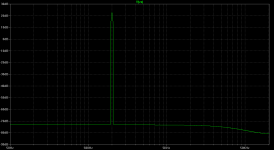
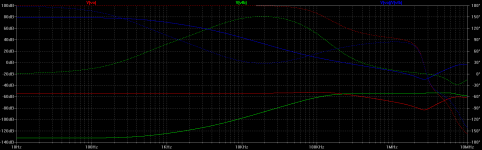
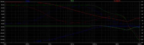
Attached is the circuit, the sim results, THD and loop gain. I hope they are readable this time.
What I did not have when I built this was a 'scope, but subsequently I confirm the amp is stable...thanks Hugh!
However, I also have experience of using the AP Sys 1 and making distortion measurements, having duplicated Doug Selfs results for the 'load invarient'
amp (built on his PCBs) so I know how critical layout earthing etc etc has to be.
Whilst we are on the Doug Self topic, the load invarient amp, despite managing sub 0.0005% ie noise floor THD at 1KHz sounded diabolical on music so I conclude that there are other things going on. I am not of the mind these are magic, I am absolutely sure there are good engineering explainations, but I don't think I am close to uncovering them all!
The sim of the Cherry shows ~0.0001% at 1KHz 40V pk to pk out into 6 ohms, pretty good. This is what very careful circuit design plus a lot of NFB does for you, but I'm not convinced it is 'musical' whatever that means.. 😕
To sum up...I guess I would describe myself as an follower of the engineering school, but without the blinkers worn by some exponents of pure math. Do I believe in magic...alchemy...no! Do I believe sub 0.01% THD+N makes good amp..no not necessarily!!😀
Comments welcome, and you can now see a bit more about me in my profile, sorry for the oversight.
And thanks to Hugh for all the tea, sympathy and coffee!
Cheers
First I must apologise in the delay getting back to this, a house and State move are partially to blame!
OK, re the sound quality, I have small loudspeakers (Quad 11L), my 'big 'speakers..KEF104.2 didn't make it our hear unfortunately. The rest of the rig is Arcam Alpha 5+ with Tricord clock used as a transport, Burr Brown 1702 based DAC (their top end demo board to be precise one of the few they made that sounded any good!) using 4 X 1702 per channel, and a sophisticated de jitter circuit and a modified Kinshaw Perception pre. Hugh's heard it both with his amps, my amps and the Cherry. By comparision we concluded the Cherry amp is a bit 'flat'...although I suspect we both like tubey, me rather more than Hugh I have to say...!
The power supply is 2 X 150VA toroids and around 10,000u per rail, the supply voltage is +/- 37V. The 10,000u is 2X 4700u split with 0.1R. I have tried various permutations of PSU and they make very little difference.
Attached is the circuit, the sim results, THD and loop gain. I hope they are readable this time.
What I did not have when I built this was a 'scope, but subsequently I confirm the amp is stable...thanks Hugh!
However, I also have experience of using the AP Sys 1 and making distortion measurements, having duplicated Doug Selfs results for the 'load invarient'
amp (built on his PCBs) so I know how critical layout earthing etc etc has to be.
Whilst we are on the Doug Self topic, the load invarient amp, despite managing sub 0.0005% ie noise floor THD at 1KHz sounded diabolical on music so I conclude that there are other things going on. I am not of the mind these are magic, I am absolutely sure there are good engineering explainations, but I don't think I am close to uncovering them all!
The sim of the Cherry shows ~0.0001% at 1KHz 40V pk to pk out into 6 ohms, pretty good. This is what very careful circuit design plus a lot of NFB does for you, but I'm not convinced it is 'musical' whatever that means.. 😕
To sum up...I guess I would describe myself as an follower of the engineering school, but without the blinkers worn by some exponents of pure math. Do I believe in magic...alchemy...no! Do I believe sub 0.01% THD+N makes good amp..no not necessarily!!😀
Comments welcome, and you can now see a bit more about me in my profile, sorry for the oversight.
And thanks to Hugh for all the tea, sympathy and coffee!
Cheers
Attachments
Hi again,
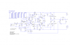
Old age setting in...those with very good eyesight will have twigged that the version of the circuit posted first time round as a jpg has a current mirror in the front end, as does the built up version. Here is the correct circuit..
The performance is virtually identical BUT I should say here that most of the amps I have heard which are disappointing use a combination of a current mirror feeding some form of enhanced VAS. This gives the best loop gain of course and lowest distortion, particularly H2.
However, I read somewhere that this combination can be prone to problems and I note that one of the mods to the ULD amp is to 'balance' the current mirror. I am not sure that the absolute precise balance is critical, the 2nd harmonic is vanishingly small anyway, but I do wonder about parasitic VHF oscillations on transients. Thoughts and comments welcome on this one.
For sure, in my experience, if you want to build a simple good sounding amp...don't use the current mirror and don't enhance the VAS, just use a good transistor!
Attachments

The patent is here: Feedback systems - Patent 4243943Are the follow articles on the web?
1) Dr Cherry's amp (published in ETI in May 1983)
2) E.M. Cherry, "Nested differentiating feedback loops in simple power amplifiers", JAES 30 295-305 (1982 May)
The circuit example in the patent is different to the one published in ETI, though.
With the mirror in place, shouldn't the resistor between base and emitter of Q6 be left out?Hi again,
Old age setting in...those with very good eyesight will have twigged that the version of the circuit posted first time round as a jpg has a current mirror in the front end, as does the built up version. Here is the correct circuit..
Absolutely...sorry...
And somewhere I have most of his papers which I downloaded from the AES, suspect they are copyrighted. I would like to see the ETI article if someone has that.
Cherry has a highly mathematical approach which makes for difficult reading, particularly the explanation of the transfer functions. I suspect the ETI presentation might be more readable.
OK, now we have the correct circuit, with the resistor removed..and 0.000078% THD...I was surprised there was not much difference, thanks Godfrey.🙂
Fourier components of V(va)
DC component:-0.114742
Harmonic Frequency Fourier Normalized Phase Normalized
Number [Hz] Component Component [degree] Phase [deg]
1 1.000e+03 2.009e+01 1.000e+00 -0.72° 0.00°
2 2.000e+03 1.242e-05 6.182e-07 164.96° 165.67°
3 3.000e+03 5.099e-06 2.538e-07 81.14° 81.86°
4 4.000e+03 9.402e-07 4.680e-08 101.55° 102.27°
5 5.000e+03 4.919e-06 2.448e-07 -24.01° -23.29°
6 6.000e+03 6.993e-07 3.481e-08 61.82° 62.54°
7 7.000e+03 4.619e-06 2.299e-07 -19.63° -18.91°
8 8.000e+03 7.233e-07 3.600e-08 67.50° 68.22°
9 9.000e+03 4.286e-06 2.134e-07 -20.39° -19.68°
Total Harmonic Distortion: 0.000078%
And ~100dB of LF loop gain.
Attachments

Last edited:
I have the ETI magazine, but no scanner.
I'll see tomorrow if I can get it scanned at a reasonable price. (Last time I asked at a local shop, they actually charged more for scanning than printing!😡)
I had a quick look at British copyright law and it looks like publisher's copyright (for magazines etc) expires after 25 years, so the ETI should be OK.
Any recommendations for file format? OCR is likely to be a dead loss, so maybe just big ugly JPEGs?
We shall see tomorrow how well 21'st century technology copes with faded printing on yellowed paper...
Thats very kind thank you. Ideal would be scan to pdf format, but really anything thats readable would do. As you know I am the expert on not readable, bits missing and extra not required bits!!
another NDFL resource is Dr Mitchell's
Nested Velocity Feedback:
http://www.personal.reading.ac.uk/~shsmchlr/miscfile/CS2007RJMitchell.pdf
Nested Velocity Feedback:
http://www.personal.reading.ac.uk/~shsmchlr/miscfile/CS2007RJMitchell.pdf
- Home
- Amplifiers
- Solid State
- New Cherry NDFL amp