Gareth Connor would be utterly amazed to find he'd emigrated! 😀
Doh...of course now I remember. My brain was OK until I emigrated.

Hi Kevin, (not Gareth!)
'With respect to the Cherry amp and Self/Lin amps sounding "diabolical", I would suggest that there are other issues in the playback system if a low-THD amplifier sounds "bad". Most people have never heard truly low-THD sound and it is impossible to correctly adjust a class-B amp for lowest distortion without a distortion analyser.'
Just to put the record straight on this, when I made these Self Invarient amps I was working for Burr Brown and had use of their AP System 1. The reason for building the amps was for a bit of fun, but also to prove that Doug's measurements were feasible. And they are, although not without a bit of messing around, grounding and signal returns absolutely critical of course.
Listening tests were performed with these amps set up as good as I could get them at the time on the System 1, and compared with a high end valve set up, which belonged to a local dealer, they were horrible. When I say horrible, poor bass, flat sound stage, poor imaging, detail, etc etc. In fact everything we accuse SS amps of.
Some 15 years later I got these amps out because I needed a low distortion power buffer to drive a output stage I built for a Burr Brown colleague. And decided to have a look at the things in detail to see if I could fix them. This is really off topic for this thread, so if anyone is interested I am happy to start a new one, but suffice it to say a number of issues were uncovered. These are applicable to all the Silicon Chip LD designs of course, which are varients of the Self designs.
For example the poor bass response is due in part to the front end power being taken AFTER the fuses, so although Doug goes to great length to filter the supplies, he has dug a deeper hole first. Not saying the new pcbs are like this but my ones from 1996 are. Many home built (and some professional 😱) amps fall into this trap.
Subsequently I have to say that I think my new Earle Weston class A valve amp is better than my modded Self amps, but now it is quite hard to tell.😛
Best wishes
Jon Pippard
Hi Guys
I have no affiliation with Doug Self. I've read his books, his articles and letters in Wireless World / Electronics World, and have referred to some of his work in my books. I find him to be just like everyone else: sometimes a genius, sometimes a fool. He can't help but be imperfect being a human being.
With respect to the subjective impressions of the low-THD amps vs others that don't measure as well: We all have an expectation of what things should sound like. This does not mean that the things that do not sound right to us are actually flawed, rather that we simply prefer something else.
A friend of mine likes his bass. He bought Velodyne subs as soon as they were on the market. He buys very good performing equipment with excellent specs. He does not like tone controls. Yet his system always sounds bass-heavy to me because (in my opinion) he has the sub level just a bit too high for correct balance. But what can I say? - he likes it that way. It excites him to play music with this EQing.
I've had many JLH amps in various systems and found the class-A thingy to be muddy when driven loud - not super loud. Similarly I find that any tube amp I've had time to experience got to sound muddy to me no matter how exciting it started off. Nominally tubes have lower distortions than SS - but this oft-repeated statement needs to be accompanied by many caveats - too many to get into here.
Much of how we interpret electronics performance will depend on the speaker system. A truly accurate speaker will show up most of the tube stuff to be erroneous in some fashion, as it will all the zero-feedback amps - depending on program material. In my experience, the guys who have been really happy with tube amps have speakers that I would not categorise as being accurate, so the particular character of the speaker might compliment the character of the amp in a way that pleases them. There is absolutely nothing wrong with that.
Jon, your remarks suggest that you are really in the tube-tone camp. You might like the JLH10 or the Pass Zen stuff. It is easy to see that you would not like the "specsman" amps as they will never satisfy what you are looking for in your musical experience. It is good to know this about yourself as it helps you focus on more likely equipment candidates.
Personally, I would like to see the high-frequency distortion plots begin their rise at a much higher frequency. CFB amps suggest such a possibility of performance, but they come with their own issues. Cherry's output-referred nested loops allows for such performance, but as you noted above, one has to very carefully determine all the values for the circuit. Ed demonstrated that you can push much closer to the Ft with his method, allowing the technology he had available to him to work quite well.
Have fun
Kevin O'Connor
londonpower.com
Not as far as I know!
Funny you should post this today, I got the prototype amps out at the weekend. Now i can actually measure things (!) I might give them a run up. Problem last time was that it was a completely new design, which worked, didn't sound that good, but with no test eqipment other than a very old 'scope it was hard to see what was going on.
I kinda got side tracked on to some other projects, not to mention moving from Sydney to Melbourne.
Pioneer did produce such amps in the 1980's, including integrated models, and their service notes make quite a point of it.
really no informations about this?Thank you therefore.
Who knows brands and models of commercial products, where is inside this topology?
Hi Tief, as far as I know Pioneer bought an interest, whether they ever used the circuit I don't know. The fact that Cherry patented this and expected royalties probably put people off. Plus the fact that although this is a way to get more NFB across the audio band, there are other ways of doing this which probably achieve similar results for audio. So pursuing this concept only to get sued was probably a waste of time for many manufacturers. There is some general theory on the web from the university of Reading UK, which shows the concept in a paper on PID theory. So it may have been used in machine/plant control loops, but I have no data on this. Certainly I have not gone any further with it. Cheers!
Hi Kevin, sorry replied to Tief before I saw your response. Also thank you John Falc, looks like Pioneer did use the technology!
I guess (as a qualified engineer), I have a lot of time for what Doug says. His approach is the only professional approach. At the same time I have heard some products which never saw an AP, and they sound really good. Strangely if you measure them, the often measure pretty good too. I'm with you, modern technology must make a better cheaper amplifier. To say a NE5534 is rubbish because it cost 30c is patently garbage. Our $200 cell phones contain technology that cost nothing yet is unimaginable only a short while back, not to mention a 1TB hard drive for $69!! But the fact remains, the ULD designs do not sound good IMO and also in many other peoples opinion. So for my next book ha ha I should explore why this is so. I have all Dougs books, who knows he might even buy a copy. Taking the front end power from the wrong place and compromising the PSRR would be one avenue worth exploring. BTW more recent work actually suggests that even a short length of wire or track can be a problem at LF where the decoupling is ineffective. So stabilised supplies or (at much lower cost) a Kelvin connection back to +/- for the front end power seems worthwhile. Thanks for your input, always appreciated!
I guess (as a qualified engineer), I have a lot of time for what Doug says. His approach is the only professional approach. At the same time I have heard some products which never saw an AP, and they sound really good. Strangely if you measure them, the often measure pretty good too. I'm with you, modern technology must make a better cheaper amplifier. To say a NE5534 is rubbish because it cost 30c is patently garbage. Our $200 cell phones contain technology that cost nothing yet is unimaginable only a short while back, not to mention a 1TB hard drive for $69!! But the fact remains, the ULD designs do not sound good IMO and also in many other peoples opinion. So for my next book ha ha I should explore why this is so. I have all Dougs books, who knows he might even buy a copy. Taking the front end power from the wrong place and compromising the PSRR would be one avenue worth exploring. BTW more recent work actually suggests that even a short length of wire or track can be a problem at LF where the decoupling is ineffective. So stabilised supplies or (at much lower cost) a Kelvin connection back to +/- for the front end power seems worthwhile. Thanks for your input, always appreciated!
Last edited:
Pioneer A-580 - NDFL Approach is in use there
good advices - thank you.
Under the website
Pioneer A-580
I read follow:
The original non switching circuit of Pioneer is adopted as a power amplifier part, and switching distortion is suppressed.
Moreover, the multiplex differential feedback (Nested Feedback Loops) which the associate professor of the Australia Monash-University cherry (that time) devised was adopted, and low-distortion-ization is realized over a wide band.
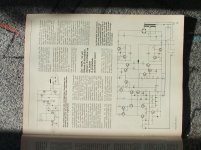
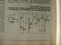
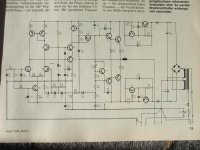
Check out the articles in follow issues from German's vintage magazine "ELRAD":Need a good amplifier circuit NDFL-type.
December 1983, February 1984 and March 1984 (amplifier project include PCB).
Maybe one of the members can upload this as copy.
In Douglas Self's Book "Audio Power Amplifier Design" I read follow:
The Cherry NDFL system applied to a four-stage amplifier to give three nested feedback loops, as used in the Pioneer A5 and A6. Pioneer launched this models 1981
Go to
https://books.google.de/books?id=ia...CDMQ6AEwAg#v=onepage&q=Pioneer "ndfl"&f=false
for more details.
This models are not so hard to find in Europe than the A-580.
Are there other brands, which use the NDFL approach in their amplifier models ?
Last edited:
Hi Tief,
Thanks for this, I think I did know this at one point, but had forgotten it! I do not know of any other amps making this claim, but then because of the patent it might not be advertised!
Since I started this thread I have met several students of Professor Cherry and they all have their own recollections of the various amplifiers he built. They also seem to think that the designs as published were not quite the same implementation as was required in real life, which adds a further tantalizing intrigue to the whole thing. Additional components got added to compensate for parasitics which were not considered in the published papers. Whilst I appreciated this is generally the case, it would be nice to know exactly what modifications were proposed. What I can say is that my amp does work, and it does produce THD1 figures IRO 0.0005%. This without inclusive Miller feedback around the output stage, which IMO is not workable. I do not have good figures for THD20 but around 0.01% at a guess.
But I also have to say that the amplifier sounds typically 1 dimensional solid state, with no real space to the image and that Hugh Deans latest creation, with 100 X more THD1 distortion sounds much better. So I have to put this technique alongside the other excellent academic articles I have read and participated in. Excellent in theory, measures well in practice (as far as my modest test capability allows) but does not live up to the expectation audibly.
As an engineer this is disappointing, but based on recent experience, not entirely unexpected!
I am fast going down the road of the minimum number of components the better and ironically this seems to work equally well for the ear and the pocket!
Of course it could be argued that once I get more than 5 components I don't know what to do with them.....
Best regards
Hi Guys
audiopip, this is a great thread and your insights are remarkable - plus you explain them clearly.
Unfortunately... there's always one of those... your impression of the low-THD amp is very common and just demonstrates to you how few low-THD systems you have heard. Most people listen to quite distorted audio and enjoy it, either because that is what they first heard as a kid and now are nostalgic for that sound - or at least that same excitement of newness - or they simply have never heard a good system and been informed about what they are hearing.
To some, it is instinctive to prefer accurate sound. That is me. I personally believe that most electronic distortions are highly unnatural inasmuch as they force our brains to go into uber-filter mode to get rid of the junk. This is especially the case with data-reduced formats. I can enjoy music even from crappy systems, unlike a friend of mine who takes it as a personal insult... or he's just a drama queen?
Most people do not have the ear training to know when they are hearing something accurate, so they just go with what "sounds good". That is perfectly fine. You can build the low-THD amp and find it lifeless because it adds no new information to the music, but then it can also reveal disparities of the rest of the system, which you otherwise might not wish to know about.
Anyway, your foray into Cherry-world is a good one! Give the result more time to sink in and there might be a revelation.
Have fun
Reviving an old thread once again, but I'm right now looking at Cherry's 60W ndfl design and simulating it, so why not use this thread, which is relevant?
Anyway, while simulating and reading things up, I have questions about what was posted long ago in post #78, about the 2 output networks.
About the version shown in the figure 9a, with the zobel on the amp's side and no resistor in parallel with the L, the equations state that 1/RC = R/L and that is the cut-off frequency corresponding to 100-300khz.
But when I tried to calculate this, the result is quite different. So what I am doing wrong?
Taking C of 100n, that would be 0.0000001 and R of 8.2, that would calculate to a little more than 1.2 million, so a little over 1.2mhz I assume. Not 100-300khz.
Then using the R/L, with L at 6.8u being 0.0000068, calculates to a little less than 1.2 million, so again, somewhat close to 1.2mhz. Again not 100-300khz, but the 2 results are rather close to each other anyway, just not what is stated it's supposed to be.
So where did I stray?
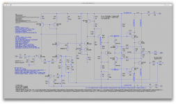
I made a sim of that NDFL 60W cherry amp from that old ETI article, using the models I have, BD139/40 for drivers, MJ802/4502 for outputs and the rest is just ltspice's library BC546C/56C.
It's not really giving stellar results, but decent.
However what I don't understand is how the open loop and closed loop gains compare.
The closed loop gain looks pretty good, with nice and flat response over a good audio band and about 30db of gain. There is a tiny bump in gain at the low end before rolling off..
But what I don't understand is what the tian probe shows for open loop gain, which is overall much lower than closed loop.
How can that be? Or Am I not placing the tian probe in the right place?
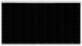
What I find interesting in that open loop gain plot is how the phase shift is "forcibly" kept from going beyond -80 degrees and that is way up there in frequency. Giving a serious amount of phase margin (above 100 degrees).
I see 3 poles. Is that right?
Those NDFL really control that phase shifting...
But Am I getting the real picture? Should that tian probe be moved somewhere else?
It's not really giving stellar results, but decent.
However what I don't understand is how the open loop and closed loop gains compare.
The closed loop gain looks pretty good, with nice and flat response over a good audio band and about 30db of gain. There is a tiny bump in gain at the low end before rolling off..
But what I don't understand is what the tian probe shows for open loop gain, which is overall much lower than closed loop.
How can that be? Or Am I not placing the tian probe in the right place?
What I find interesting in that open loop gain plot is how the phase shift is "forcibly" kept from going beyond -80 degrees and that is way up there in frequency. Giving a serious amount of phase margin (above 100 degrees).
I see 3 poles. Is that right?
Those NDFL really control that phase shifting...
But Am I getting the real picture? Should that tian probe be moved somewhere else?
Attachments
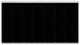
F-3dB = 194kHz !Reviving an old thread once again, but I'm right now looking at Cherry's 60W ndfl design and simulating it, so why not use this thread, which is relevant?
Anyway, while simulating and reading things up, I have questions about what was posted long ago in post #78, about the 2 output networks.
About the version shown in the figure 9a, with the zobel on the amp's side and no resistor in parallel with the L, the equations state that 1/RC = R/L and that is the cut-off frequency corresponding to 100-300khz.
But when I tried to calculate this, the result is quite different. So what I am doing wrong?
Taking C of 100n, that would be 0.0000001 and R of 8.2, that would calculate to a little more than 1.2 million, so a little over 1.2mhz I assume. Not 100-300khz.
As far as I recall E.Cherry did not state that the 100kHz to 300kHz rule applied to the output inductor.Then using the R/L, with L at 6.8u being 0.0000068, calculates to a little less than 1.2 million, so again, somewhat close to 1.2mhz. Again not 100-300khz, but the 2 results are rather close to each other anyway, just not what is stated it's supposed to be.
So where did I stray?
It simply must not significantly impede the upper end of the audio band. One could say that requires F-3dB >40kHz, but equally some may impose an F-3dB >10*20kHz.
It should also sufficiently attenuate HF being fed back into the output and thence to the -IN node.
Last edited:
I wonder if the "bump" in the LF response is due to your error in selecting the LF correction R||C?I made a sim of that NDFL 60W cherry amp from that old ETI article, using the models I have, BD139/40 for drivers, MJ802/4502 for outputs and the rest is just ltspice's library BC546C/56C.
It's not really giving stellar results, but decent.
However what I don't understand is how the open loop and closed loop gains compare.
The closed loop gain looks pretty good, with nice and flat response over a good audio band and about 30db of gain. There is a tiny bump in gain at the low end before rolling off..
But what I don't understand is what the tian probe shows for open loop gain, which is overall much lower than closed loop.
How can that be? Or Am I not placing the tian probe in the right place?
What I find interesting in that open loop gain plot is how the phase shift is "forcibly" kept from going beyond -80 degrees and that is way up there in frequency. Giving a serious amount of phase margin (above 100 degrees).
I see 3 poles. Is that right?
Those NDFL really control that phase shifting...
But Am I getting the real picture? Should that tian probe be moved somewhere else?
R13 =30k and C5 =1u47F, not 33k & 1u5F
The lost OLG must be down to using the wrong formula (posted in green at the top of the third pic).
Last edited:
I don't think, that the NDFL approach and thus the low value of THD is the reason for the mentioned sound character.Hi Tief,
Thanks for this, I think I did know this at one point, but had forgotten it! I do not know of any other amps making this claim, but then because of the patent it might not be advertised!
Since I started this thread I have met several students of Professor Cherry and they all have their own recollections of the various amplifiers he built. They also seem to think that the designs as published were not quite the same implementation as was required in real life, which adds a further tantalizing intrigue to the whole thing. Additional components got added to compensate for parasitics which were not considered in the published papers. Whilst I appreciated this is generally the case, it would be nice to know exactly what modifications were proposed. What I can say is that my amp does work, and it does produce THD1 figures IRO 0.0005%. This without inclusive Miller feedback around the output stage, which IMO is not workable. I do not have good figures for THD20 but around 0.01% at a guess.
But I also have to say that the amplifier sounds typically 1 dimensional solid state, with no real space to the image and that Hugh Deans latest creation, with 100 X more THD1 distortion sounds much better. So I have to put this technique alongside the other excellent academic articles I have read and participated in. Excellent in theory, measures well in practice (as far as my modest test capability allows) but does not live up to the expectation audibly.
As an engineer this is disappointing, but based on recent experience, not entirely unexpected!
I am fast going down the road of the minimum number of components the better and ironically this seems to work equally well for the ear and the pocket!
Of course it could be argued that once I get more than 5 components I don't know what to do with them.....
Best regards
Maybe effects through not good power supply (too small transformer), ps capacitors and/or bad design for the earth-management (GND-management) is the reason for this unwanted sonic performance.
OTOH - I don't think, that NDFL can provide same clean and smooth sound than a pure class A single ended power amp. But better sound than usual approaches with 20-50mA idle current for the output stage.
I am looking for commercial power amp devices, where is in use the NDFL topology. Unfortunately I only know several PIONEER integrated amplifier models. Thank you for advices.
Here a good paper:
http://audioworkshop.org/downloads/Edward.M..Cherry.-.A.Power.Amplifier.'Improver'.pdf
Last edited:
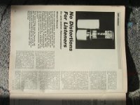
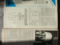
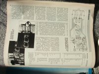
DIY Instruction ELRAD September 1988 "No Distortions For Listeners"
here the jpg copies:
any news ?I am looking for commercial power amp devices, where is in use the NDFL topology. Unfortunately I only know several PIONEER integrated amplifier models. Thank you for advices.
here the jpg copies:
Attachments
Last edited:
Hello, nice to participate in thfis forum.
Thanks for sharing the magazine photos, I lost the magazine and the circuits.
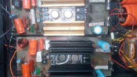
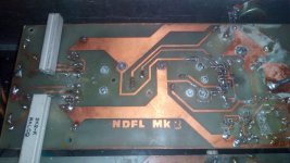
When I`was in College, in the 90s, some mate bring me a magazine`s copy from Germany and I decide assemble the amplifier. Some photos attached.
I used it for years, excellent sound, but a couple of years ago one channel burn (was repaired) and now the other channel died due to components aging (I should had used better resistors and capacitors).
Because of quarantine I have time to repair it now...
Thanks for sharing the magazine photos, I lost the magazine and the circuits.
When I`was in College, in the 90s, some mate bring me a magazine`s copy from Germany and I decide assemble the amplifier. Some photos attached.
I used it for years, excellent sound, but a couple of years ago one channel burn (was repaired) and now the other channel died due to components aging (I should had used better resistors and capacitors).
Because of quarantine I have time to repair it now...
Attachments
Are there mono power amplifier from PIONEER with NDFL in use ?
I know only the integrated versions A5, A580 and A6.
I know only the integrated versions A5, A580 and A6.
- Home
- Amplifiers
- Solid State
- New Cherry NDFL amp