Hello Mooly
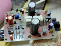
greetings rough pcb for testing its prasi design
warm regards
Andrew
That looks neat and compact.
Yes sorry for that, but I have to admit I did not remember that post. I did read most of the 1000 posts but did not remember that you had been so kind to share your files.
Edit: it looks like it's the gerber files, or am I missing something?
I was looking for the project files")
The project files are in Autodesk Eagle software. i dont know if they will be useful to you, but here they are anyway.
regards
prasi
Attachments
Hello Mooly
greetings do i have to add 680K/22PF i want to test your amp
warm regards
Andrew
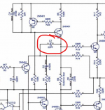
The original 22pF is mission critical and an essential component for reliable and repeatable stability margins.
Also remember that the basic amp can be tested without the FET's fitted. The output should settle to within a couple of millivolts of zero.
Attachments
The original 22pF is mission critical and an essential component for reliable and repeatable stability margins.
Also remember that the basic amp can be tested without the FET's fitted. The output should settle to within a couple of millivolts of zero.
yes you are correct. only the 680k was added by AKSA and is optional.
I should be more careful in future.
Hmm..I am being the extra cook bound to spoil Andrew's broth
.
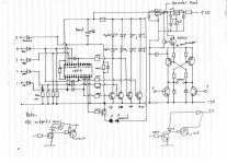
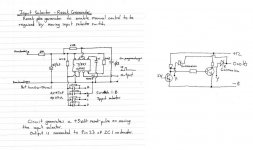
This is the Preamp in outline form (I am only just getting to grips with a PCB Software package) all the original work was hand drawn. The series /shunt switching works brilliantly and give total isolation between inputs. Even with something ridiculous like a 10volt peak/peak squarewave as an input, there is no audible breakthrough even with volume on max.
i want to make a pcb for this pre. could you tell me, whats connected at x and y ? , other inputs? if so, can we make them in proper phase and not anti phase?
and also what the psu requirements?
X and Y are logic voltage inputs using non standard levels. When X is at 0.3V and Y at -8 the selected input is off. Reverse the logic and it is on. All line level inputs (as many as you want) were summed at the opamp inverting input.
+0.3V which is right at the upper level actually was chosen (you can use zero volts) as that gives minimum on resistance of the FET while not causing the gate channel to conduct and pass the voltage as a DC offset. I used germanium diodes to clamp the levels.
The decoder was discrete and based on this diagram although the output sections were a bit different in the final build. I was going to use opto isolators but didn't in the end.
The circuit lent itself to adding remote control at a later date and that is what I did a few years later with the remote inputs simply paralleling the logic inputs. So the amp can all be used manually but if you select a different input via remote control it simply overrides the knob on the front.
An H bridge driver drove the motorised volume control.
There was also a reset generator to allow the amp control knob to regain control as soon as it was moved. I see it shows the germanium diode clamps and drive circuit.
Power supply was -/+18 volts for the opamps.
There are some more pictures here although these might be in this thread somewhere as well:
Post your Solid State pics here.
Attachments
The original 22pF is mission critical and an essential component for reliable and repeatable stability margins.
Also remember that the basic amp can be tested without the FET's fitted. The output should settle to within a couple of millivolts of zero.
Hi Mooly,
am curious wouldn't it work as well moving the 22pF to between Q4 base and Q5 collector?
You are stressing over these resistors far to much
The 10 ohm across the output inductor can be a 2 watt carbon or metal film.
The 10 ohm in the Zobel network can be similar and that will be fine for any normal use of the amplifier. In fact it would even be OK for sine testing at 20kHz at full power where it would only dissipate around 1 watt.
The 10 ohm across the output inductor can be a 2 watt carbon or metal film.
The 10 ohm in the Zobel network can be similar and that will be fine for any normal use of the amplifier. In fact it would even be OK for sine testing at 20kHz at full power where it would only dissipate around 1 watt.
- Home
- Amplifiers
- Solid State
- My MOSFET amplifier designed for music