Another Intek owner here after a schematic. If anyone out there can help it would be much appreciated.
Any chance of getting the Intek schematic from some genteleman on here? 🙂
I have exactly the same problem as described by tiefbassuebertrager on page three:
Tempting idea! I might be stupid enough to try...... 😀
I have exactly the same problem as described by tiefbassuebertrager on page three:
This causes extremly cracking while rotate the volume control, even by use of a new variable resistor therefore
PS-II If you create an ultimate "outdoor" power supply with low internal resistance, the sonic quality of this integrated amp is superb
Tempting idea! I might be stupid enough to try...... 😀
There is also the schematic from those section (post #29 pdf attachment).Any chance of getting the Intek schematic from some genteleman on here? 🙂
I have exactly the same problem as described by tiefbassuebertrager on page three:
On the last page of this pdf you will find the necessary modification steps.
BTW - I have heard, that Linn launches all schematics on demand from those models of their audio components, where Linn itself don't longer offer service, repair and maintenance.
Thus you will get the manuals from Linn.
Greetings to the Black Forest
Andreas Kirschner
tiefbassuebertragung_de
In the attachment very low resolution genuine schematics from Linn (copy from copy from copy .........................):
Attachments
Last edited:
There is also the schematic from those section (post #29 pdf attachment).
On the last page of this pdf you will find the necessary modification steps.
Thank you for your help Andreas, I followed your instructions successfully! The left channel still has a very faint crackle when I adjust levels, but it's hardly perceivable. 🙂
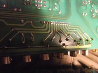
Squeezing the big capacitors in required some creative thinking though 😀
I ended up de-soldering one leg of R45/R145, and glued the capacitors to the heat sink with hot glue. The capacitors legs were just the right size to be directly soldered to the previously desoldered legs of R45/R145. 😎
Forgot to take pictures..... 😡
I checked your website, you have some nice stuff there and seem to be doing interesting projects! Found some useful links, so thank you again!🙂
I thought you might appreciate a jazz link: Home :: HGBS Studio
It's the homepage of the re-animated HGBS recording studio, better known as SABA/MPS. They are releasing music again, and also have a huge backstock of old SABA/MPS vinyl. The ultra-rare stuff has already been sold, but they still have a lot of fantastic albums in mint NOS condition. Free guided tours are also possible on appointment.
I wish you a pleasant holiday season, merry christmas and a happy new year! Greetings to the Hunsrück,
Bob

Hi, burbeck I have the same problem with the amp linn intek can you help me with the schematics? any help will be very appreciated
Hi,
I will be grateful to you if anyone can source me schematics of my Linn Kolektor Pre Amp.I desperately need the same.
I will be grateful to you if anyone can source me schematics of my Linn Kolektor Pre Amp.I desperately need the same.
check out the attachment. This schematic I had create some years ago.
Attachments
There is also the schematic from those section (post #29 pdf attachment).
On the last page of this pdf you will find the necessary modification steps.
BTW - I have heard, that Linn launches all schematics on demand from those models of their audio components, where Linn itself don't longer offer service, repair and maintenance.
Thus you will get the manuals from Linn.
Greetings to the Black Forest
Andreas Kirschner
tiefbassuebertragung_de
In the attachment very low resolution genuine schematics from Linn (copy from copy from copy .........................):
For better resolution the use of the "POWERTEK" schematic is helpful (found by electrotanya) - go to the attachment. Maybe one of the members know, where I can get a high resolution schematic version of the "INTEK" - thanks for advices.
Attachments
Last edited:
I have get a Linn Intek with extremly crackling on both channels while turning the attenuator knob. Cleaning don't remove this annoying noise.
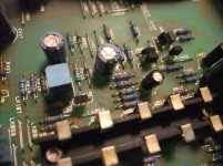
in post #29 there is a PDF attachment for the MM/MC RIAA section.
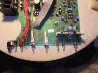
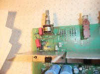
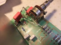
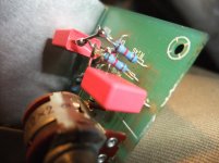
On last page of PDF is to find the schematic of the line preamp section (NE5532 is in use) include volume control and include the associated modification hints.
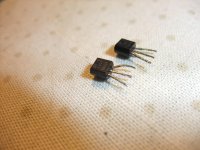
Additional I removed the jFET's for MUTE control
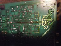
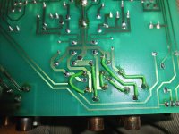
After performing this steps the amplifier works now without the above mentioned unwanted occurring crackling. Check also out the first five attached images
in post #29 there is a PDF attachment for the MM/MC RIAA section.
On last page of PDF is to find the schematic of the line preamp section (NE5532 is in use) include volume control and include the associated modification hints.
Additional I removed the jFET's for MUTE control
After performing this steps the amplifier works now without the above mentioned unwanted occurring crackling. Check also out the first five attached images
Attachments
-
 Linn INTEK 501238 volume control genuine version.jpg994.8 KB · Views: 284
 -
 Linn INTEK 501238 volume control modify version-I.jpg977.1 KB · Views: 396
 -
 Linn INTEK 501238 volume control modify version-II.jpg979.6 KB · Views: 264
 -
 Linn INTEK 501238 volume control modify version-III.jpg979.9 KB · Views: 248
 -
 Linn INTEK 501238 MUTE jFET.jpg627 KB · Views: 238
 -
 Linn INTEK 501238 Front Parts - old caps.jpg999.1 KB · Views: 330
 -
 Linn INTEK 501238 Front Parts - new caps.jpg1,004 KB · Views: 195
 -
 Linn INTEK 501238 Front Parts-I.jpg996.3 KB · Views: 190
 -
 Linn INTEK 501238 Front Parts-II.jpg979.3 KB · Views: 168
 -
 Linn INTEK 501238 Front Parts-III.jpg946.3 KB · Views: 196
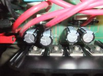
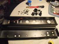
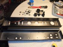
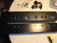
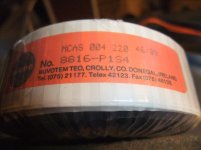
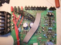
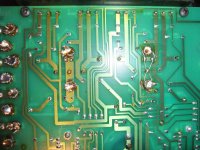
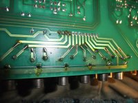
More pics. The kind of mounting requires a complete disassembly of this integrated amplifier to get to the bottom (solder side) of the PCB.
On the first image you will find a layer of fat on the PCB surface - this means, the amplifier was near a cooker in the kitchen at the previous owner.
On the first image you will find a layer of fat on the PCB surface - this means, the amplifier was near a cooker in the kitchen at the previous owner.
Attachments
-
 LINN INTEK 501238 layer of fat on the surface.jpg1,006.1 KB · Views: 162
 -
 Linn INTEK wires to speaker selector switch.jpg1,003 KB · Views: 154
 -
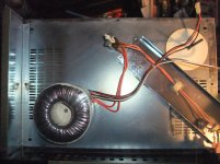
 Linn INTEK 501238 toroidal.jpg977.7 KB · Views: 145
 -
 Linn INTEK 501238 Thermal Protect.jpg988 KB · Views: 163
 -
 Linn INTEK 501238 rear.jpg1,005.7 KB · Views: 163
 -
 Linn INTEK 501238 Front Parts - old caps.jpg999.1 KB · Views: 288
 -
 Linn INTEK 501238 without PCB.jpg1,017 KB · Views: 145
 -
 DSCF6864.jpg1,001.4 KB · Views: 150
 -
 DSCF6867.jpg980.6 KB · Views: 133
 -
 DSCF6848.jpg1,023.2 KB · Views: 240
Last edited:
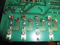
in this attachment there are discover interesting additional steps to improve soldering and contact reliability of cinch-Sockets and the big capacitors behind the rectifier.
Attachments
- Home
- Amplifiers
- Solid State
- Linn Intek Schematic required