I'm not saying discrete circuits have lower distortion than opamp circuits, they generally do not. Its just that the distortion sims of discretes are often more accurate.
Also note that the macromodels they give us freely are often not as accurate as the models they use for their internal design and testing.
To paraphrase Bruno Putzeys: "They have no desire to educate the competition" ;-)
Jan
Also note that the macromodels they give us freely are often not as accurate as the models they use for their internal design and testing.
To paraphrase Bruno Putzeys: "They have no desire to educate the competition" ;-)
Jan

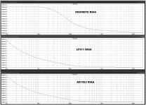
Another question, now on a different area: noise.
What does it really mean what you get by using the .noise command?
Why doesn't the different chip, on the opamp preamps, does not affect the noise results?
Isn't the noise of each opamp included in the model paramters?
The top one should be the noise of a discrete RIAA preamp. The vertical parameters would have to be widened to read actual noise differences with the opamp preamps.
Attachments
Correct, opamp2.asy is an opamp symbol, and you can use it again and again till the end of times on the same schematic, just rename it to desired opamp and put .inc "opamp".sub as many as you like, just make sure that relevant spice model is included in sub folder as you have already done for AD745J.
If you right-click on the .asy you can change the opamp it links to. Not just change the symbol name but also where it points to.
I know, easy for me to say, I RTFM ;-)
OK, we seem to be getting there.
I right click where? If I do it on file manager it doesn't give any link option.
If I click on the circuit and the chip, it doesn't get me anywhere, I can only change the name, but how to link it to the sub.
Correct, opamp2.asy is an opamp symbol, and you can use it again and again till the end of times on the same schematic, just rename it to desired opamp and put .inc "opamp".sub as many as you like, just make sure that relevant spice model is included in sub folder as you have already done for AD745J.
OK, OK. I finally got it and made it work.
Is there a way to leave a definitive link and not to write the name of the opamp everytime?
Last edited:
Another question, now on a different area: noise.
What does it really mean what you get by using the .noise command?
Why doesn't the different chip, on the opamp preamps, does not affect the noise results?
Isn't the noise of each opamp included in the model paramters?
The top one should be the noise of a discrete RIAA preamp. The vertical parameters would have to be widened to read actual noise differences with the opamp preamps.
The circuit noise may be bigger than the opamp noise, so changing the opamp doesn't change it perceptibly.
Jan
If the THD results on circuits involving are not that reliable, or real, as those from discrete designs, because of better models, then the two discrete ones are more than promising.
On one of them I doubled the supply voltage on the simulation, going from +/-15v to +/-30v, and 3rd order THD decreased considerably: from -101dB to -124dB with the original transistors: BC550/BC560.
But things improved even more, for the same +/-30v, when I swapped to KSA992/KSM1845 transistors: -135dB por 3rd order THD.
Now comes the "easy" part: build these three projects and listen to them.
I have been simulating several passive-RIAA preamps, and I started by having another look at the one suggested in the LM4562 datasheet right at the beginning.
http://www.ti.com/lit/ds/symlink/lm4562.pdf
The preamp had not performed well on the simulation. So I wanted to know why, as many people were using that chip and recommending it.
The answer seem to show when I simulated the frequency response. There a 5.6dB drop from 3KHz 50 20KHz. I can provide the asc files if anyone wants to check it.
The only explanation I can think of is that the LM4562 LTSpice model must be wrong.
Substituting the LM1115 on the same schematic gave +/- .5dB on the FR.
Eliminating the RIAA filter repeated the same fall-off, and there's no filter acting on the schematic.
Jan,
Do you know if there's a standard input voltage or output values to test preamps, including RIAA types, in THD simulations?
In power amplifiers, what I did was to set a load and get to the output just before clipping at all frequencies, then measure the THD at different frequencies.
Some people also measured the THD @ 1W into 8 ohms.
For line preamps we can follow a similar procedure, but things are more forgiving at such levels. At most you had to watch the output current level and output transistors dissipation. There are several line level standards that can be used.
Line level - Wikipedia
Which should we use?
But on RIAA, we do not have a flat (or close to) line between input and output if we inject different frequency signals. So we have to add an "anti-RIAA" filter at the input.
For an MM cartridge we can expect an output level of around 7mV, much less than for MC. So I ask: what frequency should be selected as parameter for measuring THD on a RIAA?
My feeling is that we should set the input level, so that the signal goes through the anti-RIAA filter and exits at 7mV @ 1KHz. Can you tell me if that is the way things are usually done?
Then I can test RIAA preamps set for that level and compare their THDs.
- Status
- This old topic is closed. If you want to reopen this topic, contact a moderator using the "Report Post" button.
- Home
- Design & Build
- Software Tools
- Looking for AD745 LTSpice model