Provide us with the basic information needed to understand how Vituix calculates the curves we are looking at.
Simplified explanation was here: post #871. Exceptions:
* 0 deg and 180 deg directions have also very small weighting by width of coverage sector to avoid total ignoring due to sin(0)=0. Tylka's paper has some method for this risk too. Beranek & Mellow kinda recommend not to measure to 0 deg and 180 deg at all. Better to measure towards middle point of each sector.
* If angle step is not constant or coverage of measurement sequence ends before full 0-90 deg (Half space checked in Options) or full 0-180 deg, program divides measured sector for individual measurements by splitting at the middle points of measured angles. These are weighting factors for pressure measurements. The last half sector is mirrored forward, but not outside 90/180 deg depending on Half space selection in Options window.
If you want to check the results with omni, cardioid and dipole, download VCAD_Power+DI_verify.zip file. Includes: Ideal off-axis responses generated with Enclosure tool 1.1, Directivity Index exports and Six-pack graphs.
End of filename:
H+V Both planes included in Power & DI calculation
H Horizontal plane included in Power & DI calculation
V Vertical plane included in Power & DI calculation
Summary of test:
Maximum error in DI at very low frequencies (below cone directivity range) is 0.01 dB with constant 5 deg angle step, with all plane options. Longer step would produce bigger variance.
Power = SPL to reference angle + 10log(4pi) - DI [dB], so error in power response is the same. Calculated this way in VCAD regardless of Half space setting in Options window.
Please let me know if DI=4.77 dB for ideal cardioid and dipole, and DI=0.00 dB for ideal omni are not correct.
br,
douchebag
Last edited:
Kimmo, my number one question was if you could provide the formula you used for the calculation of the power response in Vituix. I was trying to understand properly how the calculation is done in Vituix. Until now, you did not provide this information. I don't understand why you don't want to provide this background information, but there may be reasons (whatever they are).
I would expect that Vituix uses the method described by Tylka, and in particular equation (3) (see my earlier references). Hoever, I believe your comments about the workings of the Vituix calculation do not match the Tylka formula (as explained here).
As a follow-up, you also discussed the question "Does Vituix give the correct result?". This is of course also important, but it was not my primary question. "How does it work?" is a different question than "Does the code give the correct result?".
Again, these comments do not jive well with the Tylka method. There is no "sin(0)" term involved in the "weighting" of the 0° and 180° directions. I am not sure, but maybe your code really implements something else than the Tylka method?
I have to admit that I am not familiar with the theoretical power responses of these things. I therefore took another route in order to dig in a bit more:
(A) I used the Vituix diffraction calculator to generate a data set of polar SPL response data at horizontal and vertical orbits, with an angular spacing of 5°. I used the midrange model of Monkey Coffin baffle for this, simply because I had this at hand, and since this seems to be closer to a real-world situation than a theoretical omni / cardiodid / dipole.
(B) I implemented the Tylka method (equation 3) to calculate the power response. I used GNU Octave for this. The "weighting" coefficients (as Tylka calls them) I got from my code are identical to those given by Tylka, so I guess my code is not all wrong. The code should also work out of the box in Matlab, but I haven't tried.
(C) I calculated the power response using the Tylka method (equation 3) using the data from step (A).
(D) I calculated the power response using Vituix CAD using the data from step (A).
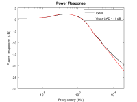
(E) I compared the power response curves I got from Tylka (step C) and Vituix (step D). See attached plot comparing the two curves.
The result is that the Vituix curve is about 11 dB higher than the Tylka curve. This could be related to different normalisation, for instance due to a 4pi term (note that 10 x log10(4*pi) = 10.99). Not a big deal so far. However, while the two curves are nicely consistent from 20 Hz to about 4 kHz, they diverge at high frequencies. Could this be due to a difference in the Vitiuix implementation as compared to the Tykla equation? Given our earlier disussion here, I wouldn't be surprised if this was related how the "weighting" in Vituix seems to be different than described by Tykla.
A ZIP file with the Tylka paper, my code, the test data, and some additional plots are available for download here (sorry, the file was too big to upload as an attachment to this post). I tried to comment the code as much as possible in order to make it easier to understand. I guess this should be useful for you to study the differences between the Tykla equation and the Vituix code.
I would expect that Vituix uses the method described by Tylka, and in particular equation (3) (see my earlier references). Hoever, I believe your comments about the workings of the Vituix calculation do not match the Tylka formula (as explained here).
As a follow-up, you also discussed the question "Does Vituix give the correct result?". This is of course also important, but it was not my primary question. "How does it work?" is a different question than "Does the code give the correct result?".
Simplified explanation was here: post #871. Exceptions:
* 0 deg and 180 deg directions have also very small weighting by width of coverage sector to avoid total ignoring due to sin(0)=0. Tylka's paper has some method for this risk too. Beranek & Mellow kinda recommend not to measure to 0 deg and 180 deg at all. Better to measure towards middle point of each sector.
Again, these comments do not jive well with the Tylka method. There is no "sin(0)" term involved in the "weighting" of the 0° and 180° directions. I am not sure, but maybe your code really implements something else than the Tylka method?
If you want to check the results with omni, cardioid and dipole,...
I have to admit that I am not familiar with the theoretical power responses of these things. I therefore took another route in order to dig in a bit more:
(A) I used the Vituix diffraction calculator to generate a data set of polar SPL response data at horizontal and vertical orbits, with an angular spacing of 5°. I used the midrange model of Monkey Coffin baffle for this, simply because I had this at hand, and since this seems to be closer to a real-world situation than a theoretical omni / cardiodid / dipole.
(B) I implemented the Tylka method (equation 3) to calculate the power response. I used GNU Octave for this. The "weighting" coefficients (as Tylka calls them) I got from my code are identical to those given by Tylka, so I guess my code is not all wrong. The code should also work out of the box in Matlab, but I haven't tried.
(C) I calculated the power response using the Tylka method (equation 3) using the data from step (A).
(D) I calculated the power response using Vituix CAD using the data from step (A).
(E) I compared the power response curves I got from Tylka (step C) and Vituix (step D). See attached plot comparing the two curves.
The result is that the Vituix curve is about 11 dB higher than the Tylka curve. This could be related to different normalisation, for instance due to a 4pi term (note that 10 x log10(4*pi) = 10.99). Not a big deal so far. However, while the two curves are nicely consistent from 20 Hz to about 4 kHz, they diverge at high frequencies. Could this be due to a difference in the Vitiuix implementation as compared to the Tykla equation? Given our earlier disussion here, I wouldn't be surprised if this was related how the "weighting" in Vituix seems to be different than described by Tykla.
A ZIP file with the Tylka paper, my code, the test data, and some additional plots are available for download here (sorry, the file was too big to upload as an attachment to this post). I tried to comment the code as much as possible in order to make it easier to understand. I guess this should be useful for you to study the differences between the Tykla equation and the Vituix code.
Attachments
Kimmo It would be useful to have an additional passive component. The complex impedance imported from file.
Did we have some short discussion about this for version 1.1? Could you mention few examples what would require this feature to version 2.0 (which is quite limitless)?
...am I the only one who finds this utterly uncalled-for name-calling...
No you not alone, technical discussions is understandable but the need for name-calling seems a bit strange step even if perfectionism/passion is the drive.
I would expect that Vituix uses the method described by Tylka, and in particular equation (3)
Please do not expect that. Tylka has not invented DI and power calculation and VituixCAD is older product than Tylka's paper. He has just one possible implementation which is not the only one. I've already mentioned Beranek & Mellow few times. Those guys represent simpler method which gives good result when pressure measurement directions are toward middle position of each sector. For example with angle step of 5 deg, measurement directions would be reference angle i.e. 0 deg, 2.5 deg, 7.5 deg, 12.5 deg, ..., 177.5 deg. That enables very simple weighting with sin() function only assuming that angle step is constant and whole sector 0-90 or -180 deg is measured.
But my life has been more complicated due to users who want "think" and do as less measurements as possible to save e.g. 5 minutes per project. So calculation in VCAD has developed over the years from very strict n' bureaucratic "measure all or I don't show you anything or at least calculate wrong" to more flexible which tries to struggle against laziness and ignorance and give some valid power & DI results. So program is packed with few workarounds, sleeve constants and custom functions which cannot be explained with simple row of Greek hieroglyphs. For example direction weighting is done with integral sine.
With this background, not much comments about your comparison. Result of VCAD looks more accurate because directivity of ideal piston increases quite constantly at HF.
I am not sure, but I suspect "the name calling" thing is in relation to my post 1162. If my post came across in an unpolite way, that was not my intention, and I apologise. However, can't see how I was unpolite or insulting in any way. I would therefore be glad if someone would explain to me what was wrong so that I can do better next time.
I am totally aware that Vituix is a great piece of software, and I applaud the creator for that! See also my recent post here.
I am totally aware that Vituix is a great piece of software, and I applaud the creator for that! See also my recent post here.
Tylka has not invented DI and power calculation and VituixCAD is older product than Tylka's paper.
Sure. The Tylka paper is just easy to get. For his equation (3), which I thought would be the basis for Vituix, he refers to a paper by Davis published in 1973. I guess that was before Vituix was born
")
He has just one possible implementation which is not the only one. I've already mentioned Beranek & Mellow few times. Those guys represent simpler method which gives good result when pressure measurement directions are toward middle position of each sector.
Could you provide a complete reference so that I can look it up?
With this background, not much comments about your comparison. Result of VCAD looks more accurate because directivity of ideal piston increases quite constantly at HF.
I am not sure. The test data are not only the result of the directivity of an ideal piston, but also baffle diffraction. Take a look at the polar plots included in the ZIP file linked in my earlier post.
Rev. 2.0.15.3 (2019-05-02)
Enclosure
* Changed initial column order of Drivers table.
* Allowed temporary column reordering by dragging column header.
* Added Hide columns and Show columns commands to context menu of Drivers table. Hiding sets column width to minimum (5px).
* Added PR checkbox to show all passive radiators only.
Could you provide a complete reference so that I can look it up?
I have the book which is copyright material. But there is just basic version equal to Tylka (1). Calculation example with Genelec 8030A is built so that simple weighting with sin() function gives good result. Tylka (3) and weighting by circular area on spherical surface (section 4) is more sophisticated implementation. My home made integral sine weighting tries to do the same, though I could change that to area calculation which is probably faster.
The test data are not only the result of the directivity of an ideal piston, but also baffle diffraction.
Power should drop 6 dB/oct with ideal piston, regardless of additional box effects. Anyway, calculation principle in your test could be fully okay though result was not (yet). Response data without very dense dips would be better for this because it does not require so high frequency resolution and exactly original frequency points. Also VCAD collapses with 8" ideal piston at about 22 kHz due to very dense response dips. Frequency axis with 48 pts/oct. limits some things.
11 dB difference is scaling to total power. It's just visually different than average power or whatever the correct term is for power response which is usually located below axial SPL.
I have the book which is copyright material.
Can you provide a full reference so I can look it up? I know the authors, but I would also need the title and possibly some other things like publisher and year of publication. You could also provide a link to a website showing the book. Just something so I understand where to look.
Wouldn't it be Acoustics: Sound Fields and Transducers? There is a new edition this month, Acoustics: Sound Fields, Transducers and Vibration. Errata and details for the various editions are at Book & papers
^That's it. Name was already mentioned in Monkey Box thread (with typo in Beranek).
P.S. I have primarily tested weighting with area calculation in VCAD. The result looks a bit worse than with existing integral sine function though the reason is probably just coincidence.
Essential is to take care that weighting factors for -180, +180 and 0 deg are compatible with number of pressure measurements (responses) in calculation. Those points have clear risk of duplicate data. For example weighting factors by Tylka look that 0 deg response in vertical plane should be skipped because factor is two times higher than relative area. Probably all -180 deg measurements too.
Last edited:
Wouldn't it be Acoustics: Sound Fields and Transducers? There is a new edition this month, Acoustics: Sound Fields, Transducers and Vibration. Errata and details for the various editions are at Book & papers
Thanks. I will ask the library to get it.
Essential is to take care that weighting factors for -180, +180 and 0 deg are compatible with number of pressure measurements (responses) in calculation. Those points have clear risk of duplicate data. For example weighting factors by Tylka look that 0 deg response in vertical plane should be skipped because factor is two times higher than relative area. Probably all -180 deg measurements too.
Sure. This actually applies to ALL points. The Tylka paper explains this nicely in the equations 10-12 and the text on page 7. Tylka also notes that the points that are redundant because they occur on both the horizontal and the vertical orbit (at theta=0° / phi=0° and at theta=180° and phi=180°) must be treated such that they are not counted twice. The details of how you implement this will depend on how your code works. I implemented it exactly the way it's done in the Tylka paper.
Weighting factors for conversion from dual plane to full sphere, with the latest built of 2.0.15.3:
0 deg = 0.00023755949249524
5 deg = 0.000950402661547924
10 deg = 0.00189357218497265
15 deg = 0.00282233048069959
20 deg = 0.00372960913729867
25 deg = 0.00460850321636333
30 deg = 0.00545232380326115
35 deg = 0.00625464891381303
40 deg = 0.00700937236947052
45 deg = 0.00771075026902158
50 deg = 0.00835344470314708
55 deg = 0.0089325643791338
60 deg = 0.00944370184656549
65 deg = 0.00988296704068173
70 deg = 0.0102470168881197
75 deg = 0.0105330807497212
80 deg = 0.0107389815067692
85 deg = 0.0108631521301764
90 deg = 0.0109046476065223
95 deg = 0.0108631521301764
100 deg = 0.0107389815067692
105 deg = 0.0105330807497212
110 deg = 0.0102470168881197
115 deg = 0.00988296704068172
120 deg = 0.00944370184656548
125 deg = 0.0089325643791338
130 deg = 0.00835344470314709
135 deg = 0.00771075026902159
140 deg = 0.00700937236947053
145 deg = 0.00625464891381305
150 deg = 0.00545232380326117
155 deg = 0.00460850321636336
160 deg = 0.0037296091372987
165 deg = 0.00282233048069962
170 deg = 0.00189357218497268
175 deg = 0.000950402661547952
180 deg = 0.000118779746247628
180 deg is half compared to 0 deg because the same direction is looped twice per plane in VCAD.
Method is still integral of sine instead of Archimedes' Hat-Box Theorem.
These are pretty much identical to those in the Tylka calculation. Here's the difference of your coefficients to those in Tylka (VCAD - Tylka):
-0.000000385112
-0.000000017364
-0.000000034597
-0.000000051566
-0.000000068142
-0.000000084200
-0.000000099617
-0.000000114276
-0.000000128066
-0.000000140880
-0.000000152623
-0.000000163204
-0.000000172542
-0.000000180568
-0.000000187219
-0.000000192446
-0.000000196208
-0.000000198477
-0.000000199235
-0.000000198477
-0.000000196208
-0.000000192446
-0.000000187219
-0.000000180568
-0.000000172542
-0.000000163204
-0.000000152623
-0.000000140880
-0.000000128066
-0.000000114276
-0.000000099617
-0.000000084200
-0.000000068142
-0.000000051566
-0.000000034597
-0.000000017364
-0.000119164858
With the exception of the last one, this is negligible. I guess you know best what to do with the last one (180°) in your code. But I am surprised it is not treated the same way as the first one (0°).
Edit: in the Tylka calculation, the first value (0.000237...) is already divided by two because the 0°/0° point is both on the horizontal AND the vertical orbit, so the point is counted twice. Therefore the coefficient is divided by two, resulting in 0.000237... . So I guess since your code uses the same value, the 0°/0° point is also counted twice. Since the 180°/180° point is also counted twice in your code (like the 0°/0° point), I believe you shouldn't divide this value by 2 again.
Last edited:
But I am surprised it is not treated the same way as the first one (0°).
This is related to polarmap and surface charts which have the same curve twice with different color. Easier for me to do everything for 180 deg twice in this big puzzle and just divide two weighting factors by 2.
This would be with Archimedes' Hat-Box:
0 deg = 0.00023794460453555
5 deg = 0.000950420026005927
10 deg = 0.00189360678173463
15 deg = 0.0028223820464633
20 deg = 0.00372967727961752
25 deg = 0.00460858741663313
30 deg = 0.005452423420667
35 deg = 0.00625476319020632
40 deg = 0.0070095004351389
45 deg = 0.00771089114930796
50 deg = 0.00835359732586745
55 deg = 0.00893272758273709
60 deg = 0.00944387438897372
65 deg = 0.00988314760874303
70 deg = 0.0102472041076021
75 deg = 0.0105332731957713
80 deg = 0.0107391777147564
85 deg = 0.0108633506068394
90 deg = 0.010904846841334
95 deg = 0.0108633506068394
100 deg = 0.0107391777147564
105 deg = 0.0105332731957713
110 deg = 0.0102472041076021
115 deg = 0.009883147608743
120 deg = 0.00944387438897372
125 deg = 0.00893272758273714
130 deg = 0.00835359732586745
135 deg = 0.00771089114930796
140 deg = 0.00700950043513891
145 deg = 0.0062547631902063
150 deg = 0.005452423420667
155 deg = 0.00460858741663313
160 deg = 0.00372967727961751
165 deg = 0.0028223820464633
170 deg = 0.00189360678173464
175 deg = 0.000950420026005927
180 deg = 0.000118972302267775
Result is usually exact but method needs averaging workaround close to 0 deg if next measurement directions to different sides (+/-) are not symmetrical.
- Home
- Design & Build
- Software Tools
- VituixCAD