Right click on any of the graphs you want to modify to open a popup menu. Click "Traces..." on the popup menu to modify the traces on that particular graph.
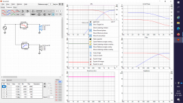
Draki is showing traces window on the SPL graph so right click on the SPL graph and then "Traces...", top left of the six-pack.
Draki is showing traces window on the SPL graph so right click on the SPL graph and then "Traces...", top left of the six-pack.
Last edited:
Is ANYONE Kind enough to check my simulation In VituxCAD
Hi.
I am simulating a budget 3 way using a Coax for mid and tweeter. Vituix Is Awesome! The reason for this is I want to experiment with an OMNI for a workspace where I will be an various places. I need to run 8 ohms for my amp.
I have done a crossover simulation and a ported cabinet simulation. Would anyone be kind enough to look at my sim and tell me if I'm even on the right track?
  The FR in the upper range is a bit lumpy and i may have some phase issues up there. Parts Express did a boombox kit using the same coax and my sim is flatter than theirs. I've tried with 3rd and 4th order for mid to tweeter but cant get it flatter. A second order xOver will i hope be simpler and cheaper?
Links to files below
Crossover
Dayton CX120-8.vxp - Google Drive
Cabinet
Dayton Audio DC200-8 Bass reflex.vxe - Google Drive
I know there are better drivers out there but I need to keep in this budget range, 8 ohm, and drivers have to be available in Australia and can be shipped to New Zealand. Shipping from US at present is riduculous... for this build anyway

Cheers.
Hi.
I am simulating a budget 3 way using a Coax for mid and tweeter.
Vituix Is Awesome! The reason for this is I want to experiment with an OMNI for a workspace where I will be an various places. I need to run 8 ohms for my amp.I have done a crossover simulation and a ported cabinet simulation.
Would anyone be kind enough to look at my sim and tell me if I'm even on the right track? The FR in the upper range is a bit lumpy and i may have some phase issues up there. Parts Express did a boombox kit using the same coax and my sim is flatter than theirs. I've tried with 3rd and 4th order for mid to tweeter but cant get it flatter. A second order xOver will i hope be simpler and cheaper?Links to files belowCrossover
Dayton CX120-8.vxp - Google Drive
Cabinet
Dayton Audio DC200-8 Bass reflex.vxe - Google Drive
I know there are better drivers out there but I need to keep in this budget range, 8 ohm, and drivers have to be available in Australia and can be shipped to New Zealand. Shipping from US at present is riduculous... for this build anyway
Cheers.
Last edited:
Member
Joined 2003
You have missed the most important part. Where are your driver measurements? Project files are next to useless without accompanying measurement data.
Based on the project file provided, I can only assume that you have traced manufacturer data with no processing for the cabinet design, driver locations are missing, acoustic offsets unknown, etc. Response data only to 45 degrees is not useful for insight of in-room and power response, so I would say that you are not on the right track.
Correct design process for VituixCAD is to use real measured data of the drivers in your cabinet using dual channel measurement. Start at the help file here and read the notes under "How do I start working with VituixCAD". There you will also find helpful guides for taking measurements for use with VituixCAD.
VituixCAD help 2.0
Without measured data, you can start learning the tools for response processing by following a guide I posted here:
VituixCAD
Keep in mind that the process will not provide reliable data for crossover design purpose, and is only a guide to aid with familiarization of the tools, ie something to keep you busy while you wait for your mic and jig parts to arrive in the mail")
Based on the project file provided, I can only assume that you have traced manufacturer data with no processing for the cabinet design, driver locations are missing, acoustic offsets unknown, etc. Response data only to 45 degrees is not useful for insight of in-room and power response, so I would say that you are not on the right track.
Correct design process for VituixCAD is to use real measured data of the drivers in your cabinet using dual channel measurement. Start at the help file here and read the notes under "How do I start working with VituixCAD". There you will also find helpful guides for taking measurements for use with VituixCAD.
VituixCAD help 2.0
Without measured data, you can start learning the tools for response processing by following a guide I posted here:
VituixCAD
Keep in mind that the process will not provide reliable data for crossover design purpose, and is only a guide to aid with familiarization of the tools, ie something to keep you busy while you wait for your mic and jig parts to arrive in the mail
Thanks for the answer. yes I was using manufacturing frd files to see if I could make something before purchasing drivers. I was not aware that a saved vituix file did not include the frd data sorry. I will repost with the data.Thanks for the link to your help file. It's a bit easier to understand than the vituix how to. The part I find the most confusing is getting cabinet data combined with crossover data. Also this will be an Omni with a difuser cone and in a round cabinet. Can I even model that in vituix?
Member
Joined 2003
It should be clear from the instructions, that regardless of the specific speaker design, the recommended method is to use real measured data, only providing calculated simulation data where you need to to overcome limitations of measuring indoors. Why use a calculated model with limited accuracy when real measurement can be completed easily and accurately. "Diffuser cone" falls under horn/waveguide type of installation, accurate calculation is very complex, however taking acoustic measurement is very simple.
It should be clear from the instructions, that regardless of the specific speaker design, the recommended method is to use real measured data, only providing calculated simulation data where you need to to overcome limitations of measuring indoors. Why use a calculated model with limited accuracy when real measurement can be completed easily and accurately. "Diffuser cone" falls under horn/waveguide type of installation, accurate calculation is very complex, however taking acoustic measurement is very simple.
He just quite literally told you why;
"I was using manufacturing frd files to see if I could make something before purchasing drivers" ?
This is still the main biggest issue with loudspeakers.
Since manufactures simply refuse to give any decent data (and the majority of the data isn't even decent), one has to estimate beforehand what works or not.
So there is nothing wrong using frd files for a rough estimate.
But yes, when the physical drivers are available measuring is necessary.
Hey thanks. I'm aware that real measurements are required. I'm just seeing if I can use the software properly first. I'm not there yet as was noted. I'll have another go then post back.
The missing files:
FRD and ZMA for the drivers
FRD ETc.zip - Google Drive
Xover Simulation
Dayton CX120-8.vxp - Google Drive
Ported Cabinet (its been pointed out this is incomplete)
Dayton Audio DC200-8 Bass reflex.vxe - Google Drive
Im not sure why Vituix makes it so confusing to merg cabinet and crossover. I still cant work it out. Why cant it be live so changes to either cabinet or crossover are reflected in the graphs?
Last edited:
Member
Joined 2003
Cabinet and crossover are two separate processes, generally cabinet design is complete well ahead of any crossover implementation. Don't be surprised that the software doesn't automatically accommodate an incorrect workflow.
Follow the process outlined in my tutorial to familiarize with the response processing process and tools to prepare manufacturer data for design. The process in that document approximates the process that one would take with real measurements, so when you buy your mic and build 2-channel jig the software process will not appear that complicated.
A quick search found this low cost mic available in Australia:
Sonarworks SoundID Reference Measurement Microphone - Sounds Easy
Your crossover design as-is is not useful at all, the manufacturer data has simple been traced with no processing for your intended cabinet, missing driver location offsets, etc. You also have Zmin of about 2 ohms which will be fairly stressful.
Last edited:
Since manufactures simply refuse to give any decent data (and the majority of the data isn't even decent)
This is the main reason why also traced data is not valuable for any crossover simulation. I have traced driver responses just once in last 35 years. Result was that money, materials and time was lost because reality was much worse than published responses. Target was passive XO so project went to trash.
Designer needs to know:
- are driver sensitivities compatible for passive crossover
- are responses smooth enough for passive crossover.
This does not require response tracing. Just looking datasheet.
Member
Joined 2003
Well, any crossover can "work", however some will work a lot better than others. The question is how accurate is the simulation vs reality. You have unknown accuracy of manufacturer data, simulated baffle effects, missing off axis information, and missing acoustic delays between drivers. Put it all together and the chances of rear world result matching the simulation is a roll of the dice, which is why I have tried to make it clear that my instructions are only for purpose of understanding the tools. Further, without full 360 degrees of measurement data you are missing out on the best features that VituixCAD has to offer which is the insight of in-room and power response and the optimization of overall speaker performance, not just basic single axis calculations.
Member
Joined 2003
Its more approximate data, in approximate data out. Nothing less than real world measurements should be used as the basis for crossover component values but traced data sheet FR combined with diffraction will do a much better job telling one if his driver spacing is correct than tools like XDIR and Edge. And that is just the beginning, it also gives useful info on boundary interference, driver excursion, and system power response. There is nothing like Vituix for predicting the performance of an array.
I don't get to do a lot of designs and I haven't been doing this for 35 years so before I start buying drivers and cutting plywood, I want to know if a design idea is worth pursuing. Vituix simulations with the best data available pre-measurement, plus driver and manufacturer reputation, is all I have to rely on. To some extent, it makes up for my relative lack of experience. Nothing wrong with starting with traced data as long as ultimately its replaced with measured data.
So let me get on the bandwagon - don't even think about reading the sticky thread on this forum about designing crossovers without measurements!
I don't understand why some of you guys says that traced data is totally crap and unusable?
That's just not really an objective assessment.
But it DOES highly depend on how good (or mostly bad) some manufacturers present their data.
The more important question above this all, is to ask where and why the traced data isn't representative?
Besides the data itself, that's mostly because of how tricky it is to simulate diffraction accurately. As well as (off-axis) interference.
So again, as long as someone is very aware of these two shortcomings, I don't see the issue of getting a very rough and global idea before spending your hard earned money on something.
So it's totally strange and very silly that one should never use it. Since it's the only way to get some idea of a speaker system beforehand.
Second to that, I actually would like to see an objective experiment where many designs were investigated beforehand and with measurements afterwards.
Based on my own professional experience, I think one will be surprised how many similarities there will be.
Yes, very obviously it won't be totally accurate.
But that's the nature of the beast, it's better than nothing.
The point is to get a decent representation of something and use it as a workable tool.
Btw, "just" looking at datasheets is maybe something that works for a couple of us here with enough experience. It's a bridge to far for people who don't have that much experience yet.
Also, especially with passive filters, the interaction between filter, frequency response and impedance of the speaker is basically impossible to predict. Or can be very tricky at best.
Even for the most experienced people among us (and those who say it's easy are dishonest to themselves)
Last edited:
- Home
- Design & Build
- Software Tools
- VituixCAD