When I got the explanation: "Oh, that's not a resistor, it's just the symbol that LTSpice needs to represent the resistance of the choke", I realized that LTSpice 'diagrams' weren't schematics that could be used as a build guide.This is supposedly a forum to actually help our fellows and not set them on a dead end.
About setting people on a dead end: Not all of us are 'smart enough' to understand the meaning of SINE ( 0 60 1000 000 1300) AC2 and similar jargon.
But LTSpice is very popular and useful. If I believed in reincarnation, I'd definitely put it on the 'to do' list for the next time around the great wheel of life. For this existence, it's not something I'll spend time with.
Back on topic:
Has anybody used DIY Layout Creator?
Software > DIY Layout Creator : DIY Fever – Building my own guitars, amps and pedals
It was recommended to me by a friend, but I haven't made time to try it out yet.
Victoriaguy,
No need to get defensive. It's like learning to swim. If you don't know how then the water will look scary and it can drown you. The longer you put off learning it the more reasons you invent in your mind why you'll never get into deep water. One invents reasons because it scares you.
I could just as easily have left off those symbols and characteristics from those input sources. It just would have invalidated the sim. Basically you can make it look just about as simple as your preferred type of schematic if you make the circuit unqualified to simulate. That is what you are missing. The extra parameters you noted weren't left in to impress you. They were for my own reference when I created it. LTspice also allow you to specify the internal resistance of any coil easily without putting in a separate resistor. I don't know how that erroneous info about a separate resistor being required got to you.
> I've seen very clear schematics drawn with MS Paint and other free drawing software packages.
Many excellent schematics were drawn by hand on paper.
My feeling is that a legible hand-draw is *faster* than wrasling a mouse and clickety restrictive interface. T-square and inking makes time comparable.
Many excellent schematics were drawn by hand on paper.
My feeling is that a legible hand-draw is *faster* than wrasling a mouse and clickety restrictive interface. T-square and inking makes time comparable.
Victoriaguy,
No need to get defensive. It's like learning to swim. If you don't know how then the water will look scary and it can drown you. The longer you put off learning it the more reasons you invent in your mind why you'll never get into deep water. One invents reasons because it scares you.
Gee, this sounds just like the 'old days' at work when anybody who asked questions about the latest re-organization idea was accused of being 'afraid of change'.
")
I have some test equipment and some decade resistor and capacitor boxes, so it's more fun for me to play with actual components than navigate the (steep and long) learning curve for something like LTspice. And, yes, I did get quite far along in Mooly's tutorial thread on using LTspice, so I don't think fear is an issue.
So, aside from LTspice, what other free or cheap drawing software packages have people used?
I agree!Many excellent schematics were drawn by hand on paper.
My feeling is that a legible hand-draw is *faster* than wrasling a mouse and clickety restrictive interface. T-square and inking makes time comparable.
Can you use Autocad?
There is is a free cad package called DraftSight.
https://www.3ds.com/products-services/draftsight-cad-software/offerings/
You could also find free electronic & electrical dwg files (Block Libraries) or draw your own.
There is is a free cad package called DraftSight.
https://www.3ds.com/products-services/draftsight-cad-software/offerings/
You could also find free electronic & electrical dwg files (Block Libraries) or draw your own.
Last edited:
I spent 41 years as a design engineer at Motorola. In the pre-PC days we hand drew a simple schematic and handed that to the draftsman, who drew a large master schematic which was photographically duplicated. The PCB's and ceramic based "hybrid modules" were also hand drawn then photographically reproduced. My home projects were done pretty much the same way. Hand drawn schematics, PCB's done with tape for traces and Mylar "footprint' stickers for each component. I had a home darkroom for photo duplication on Kodalith lithographic film.
As the mainfraim / terminal came, and was replaced by the desktop PC, we went through dozens of cad programs. Often two different departments used different non compatible systems. The company eventually settled on Mentor Graphics company wide, then abruptly switched to Cadence about 10 years ago for cost reasons. Most engineers could input their own schematics, but dedicated schematic entry people were available for those who couldn't or wouldn't. Few design engineers could do their own PCB's and none were allowed to touch the PCB on a design slated for a shipping product. There was a dedicated PCB team for that. I worked in a research / development / prototyping team for the last 12 years. There were 4 of us who did our own PCB's in a team of 30 people.
Each of these systems has its strengths, quirks, limitations and flat out roadblocks. Learning a new CAD program (schematic and PCB) would take a year to reach a good level of proficiency. Learning the secrets, backdoors, and other little tricks to get around the limitations of the program (especially Mentor Graphics) took years!
Today, I use 4 main tools for my schematics, the choice depends on what the final use for that schematic is.
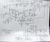
For a simple "show me how that works" schematic, I use a piece of paper. Draw the schematic, snap a picture of it with the Panasonic camera, run the picture through Nikon View for a sharp size reduced image suitable for posting on this or other forums, and done....that's it. Pic #1
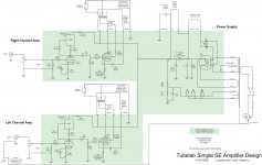
For a better quality "standardized look" schematic for the web, I use Visio. I picked up this habit at Motorola back in the 1990's before Microsoft bought the program and essentially ignored it. My current copy is Visio 2007 and it still works fine on W7, I haven't tried W10. We used it at Motorola for drawing everything from office layouts to mechanical drawings for the machine shop, to electronic schematics. The built in schematic symbols include vacuum tubes! it however has a somewhat weird UI that takes some time to learn. Output to PDF is possible. Pic #2
For a web usable schematic where simulation is possible, LTspice is a good choice. Yes, you can choose to turn off all the simulation ready stuff, but I leave it in so I can remember what I was thinking when I come back to an old project.
For a web usable schematic where a PCB will be made, I have been using Eagle. I started with Eagle in 1992 when it ran on a 286 PC using DOS. Output to PDF is also possible with Eagle. Now that Autodesk (AutoCAD) owns the company, I must look for a new option. Tubelab can't afford the $1000 per year for the pro version, which is needed because of the board size necessary for most vacuum tube PCB's. Pic #3
As the mainfraim / terminal came, and was replaced by the desktop PC, we went through dozens of cad programs. Often two different departments used different non compatible systems. The company eventually settled on Mentor Graphics company wide, then abruptly switched to Cadence about 10 years ago for cost reasons. Most engineers could input their own schematics, but dedicated schematic entry people were available for those who couldn't or wouldn't. Few design engineers could do their own PCB's and none were allowed to touch the PCB on a design slated for a shipping product. There was a dedicated PCB team for that. I worked in a research / development / prototyping team for the last 12 years. There were 4 of us who did our own PCB's in a team of 30 people.
Each of these systems has its strengths, quirks, limitations and flat out roadblocks. Learning a new CAD program (schematic and PCB) would take a year to reach a good level of proficiency. Learning the secrets, backdoors, and other little tricks to get around the limitations of the program (especially Mentor Graphics) took years!
Today, I use 4 main tools for my schematics, the choice depends on what the final use for that schematic is.
For a simple "show me how that works" schematic, I use a piece of paper. Draw the schematic, snap a picture of it with the Panasonic camera, run the picture through Nikon View for a sharp size reduced image suitable for posting on this or other forums, and done....that's it. Pic #1
For a better quality "standardized look" schematic for the web, I use Visio. I picked up this habit at Motorola back in the 1990's before Microsoft bought the program and essentially ignored it. My current copy is Visio 2007 and it still works fine on W7, I haven't tried W10. We used it at Motorola for drawing everything from office layouts to mechanical drawings for the machine shop, to electronic schematics. The built in schematic symbols include vacuum tubes! it however has a somewhat weird UI that takes some time to learn. Output to PDF is possible. Pic #2
For a web usable schematic where simulation is possible, LTspice is a good choice. Yes, you can choose to turn off all the simulation ready stuff, but I leave it in so I can remember what I was thinking when I come back to an old project.
For a web usable schematic where a PCB will be made, I have been using Eagle. I started with Eagle in 1992 when it ran on a 286 PC using DOS. Output to PDF is also possible with Eagle. Now that Autodesk (AutoCAD) owns the company, I must look for a new option. Tubelab can't afford the $1000 per year for the pro version, which is needed because of the board size necessary for most vacuum tube PCB's. Pic #3
Attachments
I've seen very clear schematics drawn with MS Paint and other free drawing software packages.
I also just use MSPaint for drawing. It's easy and fast in my experience. You can use whatever images (copy and paste) you want for your components, and I've always had an easy enough time using the simple line tools to put the circuit together.
files into KiCad and then make the board bigger
My tube amp boards are rather simple and I can re-layout one of them in an evening or two. I have done 10 layer HDI RF boards at Motorola, and I don't plan to do that again, but multi layer mixed leaded and SMD boards aren't out of the question.
I plan to try both KiCad and Design Spark before deciding on which of these, or even something else is my best choice. Obviously cost is a big deal, and I am against any subscription software, especially from a company that is trying to force that model on a long time user.
For now I am still using Eagle 5.11 since it still works, is paid for, and I have made all the tube library parts I need, and a lot of other parts, both leaded and SMD. Going forward I plan to do some more work with microprocessors, music synthesis, and RF, so the included libraries and the ability to create new parts are important. I made most of my SMD Eagle parts with a text editor, by exporting the scripts of existing parts, cutting and pasting up what I wanted, and importing the script back into a new library.
Eagle 5.11 will not read any Eagle library parts created with V6.xx or newer, so none of the modern part footprints are available to me. I have been told that both Design Spark and KiCad can import my old Eagle libraries, and that is a big deal to me.
I've seen very clear schematics drawn with MS Paint and other free drawing software packages.
I use Appleworks on an older Mac Mini. I found some symbols online a while back and I've combined some of them to draw a few oddball tubes like the 6N6G.
Unfortunately, Appleworks / Clarisworks is not usable on the latest OSX operating system. So far I haven't found anything free or super cheap that works well on my newer Mac. Fortunately I have a couple of older Macs that work well, when needed.
I just noticed that LT Spice is available for the newer OSX so I'll probably try it sometime but I really like the simple, clean look of Appleworks.
Attachments
Last edited:
Digikey has a free sim app on their site.
http://www.digikey.ca/schemeit
It's all online to SAVE YOUR WORK OFTEN.
http://www.digikey.ca/schemeit
It's all online to SAVE YOUR WORK OFTEN.
I use Appleworks on an older Mac Mini. I found some symbols online a while back and I've combined some of them to draw a few oddball tubes like the 6N6G.
Unfortunately, Appleworks / Clarisworks is not usable on the latest OSX operating system. So far I haven't found anything free or super cheap that works well on my newer Mac. Fortunately I have a couple of older Macs that work well, when needed.
I just noticed that LT Spice is available for the newer OSX so I'll probably try it sometime but I really like the simple, clean look of Appleworks.
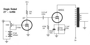
Without a coupling cap you'll send 9V into your source. Put the battery between the pot wiper and grid instead.
Fortunately I have a couple of older Macs that work well, when needed.
I too have some old Macs i use to run old software that i find irreplaceable.
dave
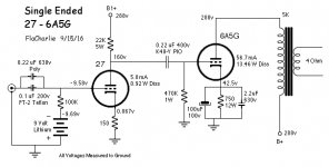
Without a coupling cap you'll send 9V into your source. Put the battery between the pot wiper and grid instead.
Ooops, posted an earlier version. I ended up removing the volume pot. This is the current configuration, which was suggested to me by Eli Duttman. I've been using it with a Fisher 100-T preamp / tuner but I plan to build a very simple tube preamp at some point. Tubes under consideration are 37, 2C22, and maybe 6V6 in triode.
Attachments
KiCad
For complex board outlines I’ve always just drawn them in AutoCAD ( with my xp-pen Deco Pro Digital Drawing Pad ) then exported to DXF then import the outline into CADSTAR or KiCad as needed. Then finish the board, export the DXF then pull that into AutoCAD to add all of the dimensions and other views. Makes a nice cross check of the original design. Although nowadays at least with CADSTAR I use their IDF interface to export the design to Solidworks so it can be used in my mech guy’s 3D model. As long as KiCad can do basic DXF import and export that should be good enough I think even for complex designs. The workflow for those involves mechanical 3D modelling so no need to reinvent the wheel on the part of the KiCad developers when it comes to drawing tools.
For complex board outlines I’ve always just drawn them in AutoCAD ( with my xp-pen Deco Pro Digital Drawing Pad ) then exported to DXF then import the outline into CADSTAR or KiCad as needed. Then finish the board, export the DXF then pull that into AutoCAD to add all of the dimensions and other views. Makes a nice cross check of the original design. Although nowadays at least with CADSTAR I use their IDF interface to export the design to Solidworks so it can be used in my mech guy’s 3D model. As long as KiCad can do basic DXF import and export that should be good enough I think even for complex designs. The workflow for those involves mechanical 3D modelling so no need to reinvent the wheel on the part of the KiCad developers when it comes to drawing tools.
- Status
- This old topic is closed. If you want to reopen this topic, contact a moderator using the "Report Post" button.
- Home
- Design & Build
- Software Tools
- Tube circuit drawing software ?