Beautifully said. I've noticed a HUGE advancement in knowledge and tools...and availability of "everything". All of the things that I learned from reverse engineering and wasting tons of money....all of that can be learned by watching someone like Joe N Tell on YouTube.
CRAZY! 2020 is better than ever before and there are a lot of young guys that are starting off with better tools and technology, let's help them out and see what inventions they will come up with. Who knows? You might PREFER them to your time tested methods and designs.
CRAZY! 2020 is better than ever before and there are a lot of young guys that are starting off with better tools and technology, let's help them out and see what inventions they will come up with. Who knows? You might PREFER them to your time tested methods and designs.
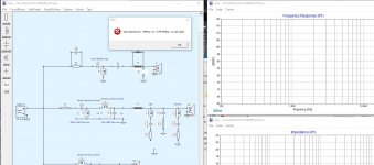
I had to redesign my schematics avoiding using circuit blocks.... This way I can continue my work but it is a major drawback for me as circuit blocks are a major facility in this simulator.
Please bear in mind I do use Xsim for more than three years now and find it really good compared with it's competitors...
Please bear in mind I do use Xsim for more than three years now and find it really good compared with it's competitors...
New feature request...
Hi Bill, I've been using XSim for quite a while, and I finally feel comfortable making a feature request") .
.
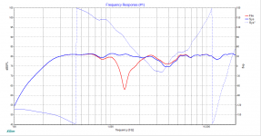
I think it would be a great additional feature to have if the software had an option to plot both the "normal" and "inverted" response curves for a driver at the same time (see example below). I think this would make it a lot easier to catch phase-tracking errors (like what's happening between 2.4 kHz and 6 kHz in the example).
Hi Bill, I've been using XSim for quite a while, and I finally feel comfortable making a feature request
.I think it would be a great additional feature to have if the software had an option to plot both the "normal" and "inverted" response curves for a driver at the same time (see example below). I think this would make it a lot easier to catch phase-tracking errors (like what's happening between 2.4 kHz and 6 kHz in the example).
Attachments
But how would a user interface be set up to do that? The circuit would have to be changed to get both curves (one of the drivers would have to be connected in each polarity, and which of the drivers to do that with? Designs with 10 or more drivers have been designed! How would a user select or avoid such a feature? If it's too obscure pretty much nobody will use it but some will get confused if accidentally activated and unintended things occur.
It seems like a lot of added nonintuitive operating complexity, when you already can check it either way by just putting your cursor over the driver chosen and tapping the 'I' key! If you want both curves on the same graph simultaneously, just do one of them and click the "Hold" button, then click the mouse in an open space on the schematic, move the cursor over the driver and tap the "I" key -- both curves on the same plot in three taps/clicks.
It seems like a lot of added nonintuitive operating complexity, when you already can check it either way by just putting your cursor over the driver chosen and tapping the 'I' key! If you want both curves on the same graph simultaneously, just do one of them and click the "Hold" button, then click the mouse in an open space on the schematic, move the cursor over the driver and tap the "I" key -- both curves on the same plot in three taps/clicks.
But how would a user interface be set up to do that? The circuit would have to be changed to get both curves (one of the drivers would have to be connected in each polarity, and which of the drivers to do that with? Designs with 10 or more drivers have been designed! How would a user select or avoid such a feature?
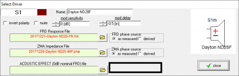
It could be activated for a single driver at a time. I've attached where the option to activate it could be included under driver properties, for example.
It seems like a lot of added nonintuitive operating complexity, when you already can check it either way by just putting your cursor over the driver chosen and tapping the 'I' key! If you want both curves on the same graph simultaneously, just do one of them and click the "Hold" button, then click the mouse in an open space on the schematic, move the cursor over the driver and tap the "I" key -- both curves on the same plot in three taps/clicks.
That approach allows you to check it for a specific x-over design - change any element in the design and the process has to be repeated from the start. Including the "plot inverted response" feature as an option for each driver (only one driver at a time) will allow the user to continuously see how the phase tracking changes when one or more of the x-over elements are changed, without having to go through the process above every time one of the x-over elements is adjusted (e.g. when using the "tune" option and the up/down keys to adjust an element's value).
Attachments
Each of us has a way of doing it.
Personally I don't find it useful to look at the reverse case at any time.
How do you track phase through the x-over region then? If you don't do this, you can end up with stuff happening off-axis (in my example a fairly sizable 3dB hump in the frequency range where our hearing is most sensitive) that can be avoided with better phase tracking through the x-over region, when the on-axis response looks good.
Last edited:
I turn on the phase plot for the individual drivers and turn it off for the system plot. I keep track by sight.
Then where I decide to let phase stray at the edges of a cross, I keep an eye on whether the system response dips appreciably below the corresponding driver response to see whether I have to hold it further in frequency.
If I decide that phase needs to track 20 degrees apart (for example), I do that by sight.
I would second that - you can change the trace thickness so the graph is better readable and just use phases of separate drivers.
I think this was brought up by someone and wasn`t met with lots of enthusiasm but what happened to that idea to add transfer functions for different crossovers?
I think this was brought up by someone and wasn`t met with lots of enthusiasm but what happened to that idea to add transfer functions for different crossovers?
Howdy,
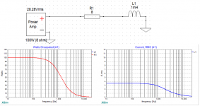
I was wondering why XSim calculates apparent power while showing power dissipation data and not true power?
I don't think it does. It calculates (or at least is supposed to calculate)
(current^2)*(real part of impedance),
which is true power dissipation.I just checked, looks right to me.
Attachments
Last edited:
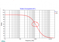
??? The graph shows 61.8W at 1kHz. It is I**2 * R. Actual dissipated power. Dissipated power has no phase angle, square the current and phase is meaningless. R has no phase. Force a current through a resistor, it forms heat, it doesnt care what phase that current is relative to anything else. Imagine the voltage source and inductor hidden in a box, only current flowing out through a resistor and back in again. Does the phase of the currenr matter? Phase with respect to what? The voltage across the resistor will be in phase with the current through the resistor, because that's what resistances do.
- Home
- Design & Build
- Software Tools
- XSim free crossover designer