I measured the same board just that I replaced the LM337N from TI with a normal LM337 from Fairchild. Looking at the results it's clear that the LM337N actually does have better PSRR performance for simple/Cadj/denoiser and dienoiser versions.
So if you want to get the best performance from LM337 you can use TI's LM337N version, just that it's double the price of TI's regular LM337.
I added these measurements over the LM337N ones for comparison. All other values/parts remained the same, I just replaced the regulator.
I suspect this difference to be present in the LM317 vs LM317N comparison.
Attachments
I retook the LM317 measurements. I reset the pcb to positive version, and tried LM317N from TI, LM317 from ST, LM338 from TI and LT1084.
I used 470uF+100uF filter capacitance for LM317N/LM317 from ST/LM338. For LT1084 I needed a higher measurement dynamic range so I used 220uF for filter cap. Still not sure if I could measure the dienoiser ripple for LT1084, but if it's lower it should be just few dB. I think lowering the input capacitance further would not make for the 1.25V or so min voltage across the regulator, on input ripple lowest point.
For Cadj measurements I used a 220uF Cadj capacitor.
The attached pictures are as follows:
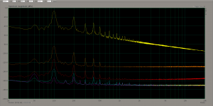
1. PSRR for LM317N. Simple regulator measures at 64dB. Cadj version measures 83.5dB. Denoiser measures 111.9dB and dienoiser measures 132.7dB.
2. PSRR for LM317 from ST. Simple reg 61.1dB, Cadj 79.4dB, denoiser 108,2dB and dienoiser 128.8dB.
3. PSRR for LM338. Simple reg 58.7dB, Cadj 77.83dB, denoiser 106.3dB and dienoiser 127.9dB.
4. PSRR for LT1084. Simple reg 80.22dB. Cadj 99.5dB. Denoiser 128dB and dienoiser 146.65dB. I'm not really sure if this is the lowest, LTSpice sim doesn't match anyway. It should be 136dB for dienoiser and 113dB for denoiser. So around 23dB difference. Seeing the measured denoiser value, the dienoiser should measure at 151dB acording to the LTSpice difference between de/dienoiser.
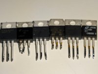
5. A photo of all tested regulators.
The voltage setting resistors were 200R/1.6K for around 11.3Vout, with a 150R load resistor.
I used a Panasonic FC 100uF/63V (EEUFC1J101L) for LM317N/LM317 from ST/LM338. For the LT1084 I used a Panasonic FR 470uF/25V (EEUFR1E471L).
Compensation network was just 1x22nF + 2x10nF sandwiched for LM317N/LM317 from ST/LM338, and 2x22nF + 1x10nF + 3.3R for LT1084.
As an observation the LM317N showed a bit less performance than LM337N.
Archives contain the graphs with cursor at point of measurements. I also included the noise measurements for each version.
I used 470uF+100uF filter capacitance for LM317N/LM317 from ST/LM338. For LT1084 I needed a higher measurement dynamic range so I used 220uF for filter cap. Still not sure if I could measure the dienoiser ripple for LT1084, but if it's lower it should be just few dB. I think lowering the input capacitance further would not make for the 1.25V or so min voltage across the regulator, on input ripple lowest point.
For Cadj measurements I used a 220uF Cadj capacitor.
The attached pictures are as follows:
1. PSRR for LM317N. Simple regulator measures at 64dB. Cadj version measures 83.5dB. Denoiser measures 111.9dB and dienoiser measures 132.7dB.
2. PSRR for LM317 from ST. Simple reg 61.1dB, Cadj 79.4dB, denoiser 108,2dB and dienoiser 128.8dB.
3. PSRR for LM338. Simple reg 58.7dB, Cadj 77.83dB, denoiser 106.3dB and dienoiser 127.9dB.
4. PSRR for LT1084. Simple reg 80.22dB. Cadj 99.5dB. Denoiser 128dB and dienoiser 146.65dB. I'm not really sure if this is the lowest, LTSpice sim doesn't match anyway. It should be 136dB for dienoiser and 113dB for denoiser. So around 23dB difference. Seeing the measured denoiser value, the dienoiser should measure at 151dB acording to the LTSpice difference between de/dienoiser.
5. A photo of all tested regulators.
The voltage setting resistors were 200R/1.6K for around 11.3Vout, with a 150R load resistor.
I used a Panasonic FC 100uF/63V (EEUFC1J101L) for LM317N/LM317 from ST/LM338. For the LT1084 I used a Panasonic FR 470uF/25V (EEUFR1E471L).
Compensation network was just 1x22nF + 2x10nF sandwiched for LM317N/LM317 from ST/LM338, and 2x22nF + 1x10nF + 3.3R for LT1084.
As an observation the LM317N showed a bit less performance than LM337N.
Archives contain the graphs with cursor at point of measurements. I also included the noise measurements for each version.
Attachments
-
LT1084.zip430.3 KB · Views: 95
-
LM338.zip433.8 KB · Views: 88
-
ST_LM317.zip435 KB · Views: 89
-
LM317N.zip434.1 KB · Views: 83
-
 regs.jpg375.2 KB · Views: 158
 -
 LT1084_PSRR.png90.3 KB · Views: 423
 -
 LM338_PSRR.png92.1 KB · Views: 422
 -
 ST_LM317_PSRR.png92.4 KB · Views: 432
 -
 LM317N_PSRR.png101.6 KB · Views: 450
Last edited:
In this post I'll attach the measurements for the SMD dual board using SMD LM317N/LM337N from TI.
For the LM317N I used 100uF input filter cap, and 150uF for LM337N. Voltage setting resistors were 220R/2K for 12.6Vout, with 270R load.
For LM317N I used the following network for output capacitor:
2x10uF 1206 + 150mOhm 0805 + diy 30nH.
For LM337N:
3x10uF 1206 + 27mOhm 0805 + diy 30nH.
The pictures attached here are as follows:
1. PSRR for LM317N. Denoiser measured at 110.6dB and dienoiser at 127.2dB.
2. PSRR for LM337N. Denoiser measured at 115dB and dienoiser at 130.7dB.
The zip files contain measurements with cursor at points of measurement for PSRR and noise. I also included photos for the output capacitor network.
The three legged regulator pcbs arrived last days and hope I have the time to assemble and test them for SMD LM3x7N and LT3082. I'll also post measurements for LT3082 on the SMD pcb that I already measured LM3x7N on.
Attachments
Also want to mention that since the LM338 measures so good (at the 100mA or so), I want to design a pcb for it as it seems interesting for it's current output capability.
But for 5A output this requires TO220 diodes and high value filter capacitors.
The dienoiser performance measured 1dB lower than a regular LM317. Noise seems the same as LM317. Curious if PSRR performance holds at higher current.
But for 5A output this requires TO220 diodes and high value filter capacitors.
The dienoiser performance measured 1dB lower than a regular LM317. Noise seems the same as LM317. Curious if PSRR performance holds at higher current.
@Trileru, if you would pick a version for analog and digital, what would those be? As I remember, LT108x are gives lower noise but lacks in bandwidth. I have bunch of LT's and I wonder about drawbacks of these comparing LM's. I also have some boards with LM2931 with separate Adj and GND pins.
Regarding compensation caps, did you observe any difference between film types and ceramics?
Regarding compensation caps, did you observe any difference between film types and ceramics?
Last edited:
As I remember, LT108x are gives lower noise but lacks in bandwidth.
I don't see it as lower noise with dienoiser. LM317 has better noise performance with dienoiser.
The only reason to use LT108x is for their increased current capability or PSRR.
For digital I went with LT3082+denoiser for my DAC. I went with LT3082+denoiser for everything actually, apart from the negative analog rail, where I used the smd LM337N.
I put CLC for all three main rails, digital and analog +/-.
As a general rule I would use LM317 really. Unless the 1.5A is not enough. Just put a LC filter in front for digital stuff. Use regular LM317. The end result should be very very good. Always use Panasonic FC 100uF/63V as output cap for LM317, always use Panasonic FR 470uF/25V (the 20mm long version) as output cap for LM337.
I only used ceramic caps, and I think Elvee recommended them as well, but can't remember. Film caps shouldn't be needed as compensation caps.
I did notice that ceramic output caps are microphonic in testing, and I'd avoid using the RLC smd network for output cap if possible. The two capacitor models I mentioned always worked fine for me. Even with LT3082+denoiser.
The problem is not that I insist to use film caps and LT's. I asked them because I have them. I don't need more current. I didn't check your diy friendly tht pcb layouts but do all of them use ceramics for compensation? You sound like you never measured regs with film caps.
Yes all boards have 0805 footprints for C and R. I never used film caps for compensation network (or at least I don't remember). Only ceramics.
There's also the thing that for low output voltage like 3.3V LM317+de/dienoiser does not perform so good. In that case I'd say LT3082+denoiser should do the trick. LT3082+denoiser works fine with that Panasonic FR 470uF/25V (20mm long version) as output cap and also doesn't need any compensation.
Any advantage of one over the other? I used smd ceramic caps in testing as it was easier for me to stack them. With tht film caps it would have been more complicated.
I've got some bad news about the LT3082+denoiser thing. Apparently I didn't wait long enough while taking the measurements. I got hyped that it was a real low 100Hz value and immediately started the linear averaging. Seems like if I waited more I would have seen that the ripple creeps up slowly to a pretty mediocre overall PSRR performance.
This happens with denoiser and also dienoiser.
I've made a screen capture that I uploaded here:
Imgur: The magic of the Internet
The first blip is when I power the board, takes some time for caps to charge up and when the voltage starts rising on the output there's that second blip, and then the ripple seems really low, buried in the noisefloor. I did make some linear averaging few times in the gif for short while so you get an idea of what I'd see, but I switch to no averaging so you see the behavior. The ripple starts creeping up in time.
I'm very sorry for this. I'm retracting any claims about LT3082+denoiser. It was a bad way to go about it, I should have tested it more. This is most likely what happened when I tested it the first time.
It might work, but it might be more complicated than I thought. I don't have the knowledge nor the tools to attempt to make it work.
No, not really. Ceramic caps will generally be more lossy, which could be an advantage to damp unwanted oscillationsAny advantage of one over the other?
I made some measurements for higher current output. I used LM317N with the same 11.3Vout and I used a higher power 8R load resistor. With connections and wires it came out at around 9R. I measured the current with the dmm and it was around 1.25A.
I had to increase the output capacitance for this current level, so to be able to have enough headroom for the capacitance multiplier Vdrop as well. I put three capacitors in parallel and the total capacitance came out at around 3400uF.
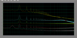
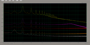
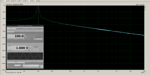
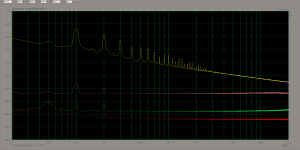
I attached a photo with comparisons between different configurations. My 0dB is set at 1.3V in ARTA.
Yellow trace is the input ripple, measured at -6.5dB.
Orange trace is Cadj (220uF) which measured at -84dB, so a total of 77.5dB for PSRR.
Red trace is denoiser which measured at -112.6dB so a total of 106.1dB for PSRR.
Green trace is dienoiser which measured at -134.2dB so a total of -127.7dB for PSRR.
The pink trace is the dienoiser with capacitance multiplier in circuit. At 100Hz it measured -153.3dB so a total of 146.8dB or more, as I think my measurement is capped at this low level. Theoretically the capacitance multiplier should add extra -56dB so the total PSRR should be at the -190dB mark, but I can't measure that low, and the ripple is under the noisefloor.
The difference between Cadj and denoiser is 28.6dB which is the same as the measurement for 100mA output.
Compared to measurements at 100mA for the same regulator, Cadj measured 7.2% worse performance, denoiser 5.2% worse and dienoiser 3.8% worse.
I think there shouldn't be drastic changes at 1.5Aoutput.
Included zip files contains the graphs with cursors at point of measurement and also there's the noise measurements for each as well.
edit: also I noticed I had 5R in series with the comp caps, I had a tht footprint and I forgot I put the 5R. The boards I posted have smd footprints for both R and C. So for all previous measurements on the LM3x7 board you have to add 5R for all compensation network values I posted. I'm not sure how much it matters or affects performance, seems to have worked fine.
This measurement had 1x22nF + 2x10nF caps for comp cap and the 5R in series. I used the same Panasonic FC 100uF/63V I used before as output cap.
I had to increase the output capacitance for this current level, so to be able to have enough headroom for the capacitance multiplier Vdrop as well. I put three capacitors in parallel and the total capacitance came out at around 3400uF.
I attached a photo with comparisons between different configurations. My 0dB is set at 1.3V in ARTA.
Yellow trace is the input ripple, measured at -6.5dB.
Orange trace is Cadj (220uF) which measured at -84dB, so a total of 77.5dB for PSRR.
Red trace is denoiser which measured at -112.6dB so a total of 106.1dB for PSRR.
Green trace is dienoiser which measured at -134.2dB so a total of -127.7dB for PSRR.
The pink trace is the dienoiser with capacitance multiplier in circuit. At 100Hz it measured -153.3dB so a total of 146.8dB or more, as I think my measurement is capped at this low level. Theoretically the capacitance multiplier should add extra -56dB so the total PSRR should be at the -190dB mark, but I can't measure that low, and the ripple is under the noisefloor.
The difference between Cadj and denoiser is 28.6dB which is the same as the measurement for 100mA output.
Compared to measurements at 100mA for the same regulator, Cadj measured 7.2% worse performance, denoiser 5.2% worse and dienoiser 3.8% worse.
I think there shouldn't be drastic changes at 1.5Aoutput.
Included zip files contains the graphs with cursors at point of measurement and also there's the noise measurements for each as well.
edit: also I noticed I had 5R in series with the comp caps, I had a tht footprint and I forgot I put the 5R. The boards I posted have smd footprints for both R and C. So for all previous measurements on the LM3x7 board you have to add 5R for all compensation network values I posted. I'm not sure how much it matters or affects performance, seems to have worked fine.
This measurement had 1x22nF + 2x10nF caps for comp cap and the 5R in series. I used the same Panasonic FC 100uF/63V I used before as output cap.
Attachments
Last edited:
I had to increase the output capacitance for this current level, so to be able to have enough headroom for the capacitance multiplier Vdrop as well.
I meant filter capacitor value, not output capacitor.
I again re-calibrated ARTA, seems I had it wrong and didn't really find much info on this. RickRay had a good hunch that the calibration in ARTA should result in reading any dBV value related to 0dB=1V, irrespective of the calibration value in mV that ARTA calculated.
I used REW for calibration, and using the same value in ARTA seems to result in believable measurement values.
REW calibration found 1.47Vrms as my max input signal, that translates to 2079mVpeak that I put in ARTA calibration. I had 1300mV before, ARTA's calibration is not reliable, it gives varying results. REW calibration values seems to get it right.
I also measured a 1k resistor and also 4x820R in parallel for a measured total of 204R. Looking up the thermal noise of this value it should be -174.8dB at room temperature, and this too checks out. Also with a 1Vrms input signal the ADC now reads -1.6dB, and that's good enough I think.
I retook measurements for LM317N, both at 100mA and at 1.25A output, at 11.3Vout, with around 3400uF filter capacitance. Measured PSRR for dienoiser, denoiser and Cadj, with noise measurements for each. All dBV values are related to 0dBV as 1V.
For 100mA total PSRR:
Cadj measured 85dB
Denoiser measured 116.7dB (31.7dB from Cadj)
Dienoiser measured 121.45dB, just 4.75dB from denoiser but ADC might be the limit here. I can go down to only -148dBV or so.
For 100mA noise:
Cadj -136dBV, around 158nV/sqrtHz
Denoiser -164.77dBV, around 5.7nV/sqrtHz
Dienoiser -176.92dBV, around 1.4nV/sqrtHz
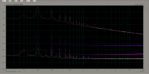
For 1.25A total PSRR:
Cadj measured 77,8dB
Denoiser measured 106dB (28.1dB from Cadj)
Dienoiser measured 129.16dB (23dB from denoiser)
Dienoiser + capacitance multiplier measured 145dB (or more, measurement limited by ADC or LNA or EMI)
Cadj measures 8.5% worse than at 100mA and denoiser measures 9.2% worse than at 100mA. I don't know where the dienoiser absolute value is for 100mA.
For 1.25A noise:
Cadj -134.9dBV, around 180nV/sqrtHz
Denoiser -164.1dBV, around 6.25nV/sqrtHz
Dienoiser -176.57dBV, around 1.48nV/sqrtHz
Having >=3300uF filter capacitance means you wouldn't need the capacitance multiplier for 100mAout. But using the capacitance multiplier with the dienoiser at 1.25Aout makes it measure as the dienoiser without capacitance multiplier at 100mAout.
Attached pictures are as follows:
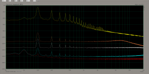
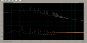
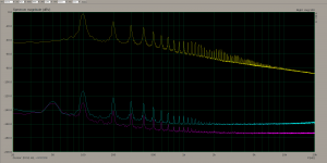
1. PSRR for 100mAout
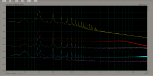
2. PSRR for 1.25Aout. I also added the dienoiser+cap multi
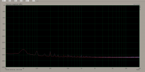
3. Comparison between 100mA dienoiser and 1.25A dienoiser+cap multi. Red trace is 100mA dienoiser without cap multi.
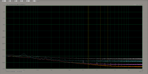
4. Noise comparison between 1k resistor, 204R resistor, LNA input shorted and last one ADC input shorted.
5. 1Vrms input into ADC and measured in ARTA.
Using a 100Hz 1Vrms input signal (measured with dmm which is true RMS) ARTA reads it as -1.6dBV or 0.83Vrms. Since it checks on both the high and low end I think this should be my most accurate measurement.
There's some higher LF noise but that might be related to my ADC, shows it when the input is grounded. This might be due to the nature of this ADC, being the integrated audio card from a PC motherboard.
I attached all individual graphs with cursor at point of measurement.
Seems I can't measure PSRR higher than 145dB or so. I'll check this on other boards.
I used REW for calibration, and using the same value in ARTA seems to result in believable measurement values.
REW calibration found 1.47Vrms as my max input signal, that translates to 2079mVpeak that I put in ARTA calibration. I had 1300mV before, ARTA's calibration is not reliable, it gives varying results. REW calibration values seems to get it right.
I also measured a 1k resistor and also 4x820R in parallel for a measured total of 204R. Looking up the thermal noise of this value it should be -174.8dB at room temperature, and this too checks out. Also with a 1Vrms input signal the ADC now reads -1.6dB, and that's good enough I think.
I retook measurements for LM317N, both at 100mA and at 1.25A output, at 11.3Vout, with around 3400uF filter capacitance. Measured PSRR for dienoiser, denoiser and Cadj, with noise measurements for each. All dBV values are related to 0dBV as 1V.
For 100mA total PSRR:
Cadj measured 85dB
Denoiser measured 116.7dB (31.7dB from Cadj)
Dienoiser measured 121.45dB, just 4.75dB from denoiser but ADC might be the limit here. I can go down to only -148dBV or so.
For 100mA noise:
Cadj -136dBV, around 158nV/sqrtHz
Denoiser -164.77dBV, around 5.7nV/sqrtHz
Dienoiser -176.92dBV, around 1.4nV/sqrtHz
For 1.25A total PSRR:
Cadj measured 77,8dB
Denoiser measured 106dB (28.1dB from Cadj)
Dienoiser measured 129.16dB (23dB from denoiser)
Dienoiser + capacitance multiplier measured 145dB (or more, measurement limited by ADC or LNA or EMI)
Cadj measures 8.5% worse than at 100mA and denoiser measures 9.2% worse than at 100mA. I don't know where the dienoiser absolute value is for 100mA.
For 1.25A noise:
Cadj -134.9dBV, around 180nV/sqrtHz
Denoiser -164.1dBV, around 6.25nV/sqrtHz
Dienoiser -176.57dBV, around 1.48nV/sqrtHz
Having >=3300uF filter capacitance means you wouldn't need the capacitance multiplier for 100mAout. But using the capacitance multiplier with the dienoiser at 1.25Aout makes it measure as the dienoiser without capacitance multiplier at 100mAout.
Attached pictures are as follows:
1. PSRR for 100mAout
2. PSRR for 1.25Aout. I also added the dienoiser+cap multi
3. Comparison between 100mA dienoiser and 1.25A dienoiser+cap multi. Red trace is 100mA dienoiser without cap multi.
4. Noise comparison between 1k resistor, 204R resistor, LNA input shorted and last one ADC input shorted.
5. 1Vrms input into ADC and measured in ARTA.
Using a 100Hz 1Vrms input signal (measured with dmm which is true RMS) ARTA reads it as -1.6dBV or 0.83Vrms. Since it checks on both the high and low end I think this should be my most accurate measurement.
There's some higher LF noise but that might be related to my ADC, shows it when the input is grounded. This might be due to the nature of this ADC, being the integrated audio card from a PC motherboard.
I attached all individual graphs with cursor at point of measurement.
Seems I can't measure PSRR higher than 145dB or so. I'll check this on other boards.
Attachments
-
1.25A.zip438.9 KB · Views: 87
-
100mA.zip332.2 KB · Views: 80
-
 1Vrms_ADC_input.png129.8 KB · Views: 112
 -
 noise_comparison.png97.7 KB · Views: 354
 -
 dienoiser_100mA_vs_1.25A_cm.png74.4 KB · Views: 352
 -
 1.25A_PSRR.png92.5 KB · Views: 358
 -
 100mA_PSRR.png89.8 KB · Views: 375
 -
LNA_noise.zip192.3 KB · Views: 81
Probably a stupid question, or not that important.
Have you tried a measurement with RC input filter, with different values, compared to a single cap or a CM?
Simulations in LTSpice show significant improvement with LR filter, and it's much simpler than CM.
Have you tried a measurement with RC input filter, with different values, compared to a single cap or a CM?
Simulations in LTSpice show significant improvement with LR filter, and it's much simpler than CM.
The smd versions have CLC input filtering.
Depends on how much performance you're looking for, how much space would the required capacitors take on the pcb, they also might be more expensive than a simple cap multi.
What RC values did you use? The capacitance multiplier as I configured it should offer about 56dB of PSRR at 100Hz.
You should also check the Vdrop across the resistor, and also dissipated heat.
With purely passive filters, there is no need to measure anything: the attenuation at a frequency brought by the additional filter will simply multiply (or add in dB/log) with/to the regulator's.Have you tried a measurement with RC input filter, with different values, compared to a single cap or a CM?
That only applies to PSRR of course: the noise will remain unchanged, and the load regulation and LF output impedance might even be slightly degraded, because the load change will be reflected to some degree at the input, especially with a RC filter
- Home
- Amplifiers
- Power Supplies
- D-Noizator: a magic active noise canceller to retrofit & upgrade any 317-based VReg