But the other one you got works, right? Mysterious. The Mosfets are the right type confirmed in the sick one? The PMOS and NMOS positioned at their right places I mean. And they do show 4-5V Vgs on M1 and 3-4V Vgs on M2? Between first and last leg the Vgs of each can be measured when the system is powered.
Yes, my first Ubib have had a quick completion, and since then is very celebrated, better than Ref-D (even unfair, Ubib win without 'boutique' capacitors). I agree is strange mistery. Mosfets are properly on their place. M1 Vgs is 5v., M2 is 3,2v but only first seconds, after that slowly decreasing on a par, I must switch off before reaching 5v. output, to prevent a breackdown to 0v. could damage Q1 BC327.
Board is set to give 13v.,adjusting trimmer VR1 together with wrr, around 3k3, but no way can't reach anything higher than 7v. output.
No load and off, probe from Vout to 0v.:
Healthy reading is climbing like a capacitor till infinite (no reading).
Damaged board reading also climbs, but slower and locked to around 5k. Ohm.
Now i see C2 220uf reversed on defective board, but always thought thouse Nichicon BP are non polar.
It's worth to switch?
Healthy reading is climbing like a capacitor till infinite (no reading).
Damaged board reading also climbs, but slower and locked to around 5k. Ohm.
Now i see C2 220uf reversed on defective board, but always thought thouse Nichicon BP are non polar.
It's worth to switch?
Last edited:
Now i see C2 220uf reversed on defective board, but always thought thouse Nichicon BP are non polar. It's worth to switch?
BP are both ways positioning caps. But there could be some dodgy one or got overheated in soldering, became leaky and loses the Vref that its there to filter? Because we are in the twilight zone of failure scenarios now, if you will try change M2, change C2 also, even with Panasonic polar to see what happens.
Hi Salas, you got here when mentioned cleaning flux. Now is fixed the board, a relief, altrough it was clean loocking I reclean but this time with a lot of alcohol, almost submerged, trying to fill inside terminal blocks, etc.. and it works!
I use high silver content solder, which need extra amount of flux and temperature to ensure proper joint. And althrough I always clean right after, for sure not enough below or inside some places. Never is enough advice againts conductivity of solder paste. I feel very grateful and sorry the long.
I use high silver content solder, which need extra amount of flux and temperature to ensure proper joint. And althrough I always clean right after, for sure not enough below or inside some places. Never is enough advice againts conductivity of solder paste. I feel very grateful and sorry the long.
Last edited:
Lessons learned:
- When weird things happen, do open output impedance checks also, as in post #740. If readings are low, probably something leaks.
It may be conductive flux residue. Use 0.5mm lead solder wire with internal flux if possible, don't add flux externally in places not strictly necessary, and clean well.
- Mosfets have very high impedance gates, this one is a high open loop gain and wide bandwidth circuit that may get compromised from leftover flux or dirt and puzzle you.
I feel very grateful and sorry the long.
No problem, its nice troubleshooting read for the builders. It will help some out of an odd failure trap in the future. By the way, your REF-D other reg has JFET mod or not?
I remember Cardas solder is recommended, I hesitated use lead solder as hazarous in first but I will reconsider, thanks advice.
I thought profesional printed circuit board cleaners have acetone (nails cleaners) mixed to alcohol. But don't know how much to add.
Red-D has Jfet mod. already but in comparison not sure how much injuried by the still there three 120ohm basic resistors. Ubib is populated allresistors with non magnetic, low ppm, etc..
Otherwise Ubib has maybe not bad Nichicon but in Ref-D is expensive combo 6800uf + 1000uF Mundorf AG+.
Ubib easy wins Red-D in that situation.
Dirty PCB crushes PSRR!I hesitated use lead solder as hazarous in first but I will reconsider, thanks advice.
Lead is hazardous if one sucks on the PCB, or breathes the fumes from a soldering station. I would imagine that if you were using solder-paste for surface mount components you could ingest lead if you weren't careful.
In the US the problems were traceable to peeling paint using Pb as pigment before TiO2 came into prominence. Children eat paint chips! Tetra-methyl lead (TML), tetra-ethyl lead (TEL) used as octane boosters. It was found that dust near the toll booths on parkways, bridges and tunnels were contaminated with organo-lead compounds, otoh, "Battle of Britain" would have been lost without TEL.
Just like JOIMONF, I had my fair share of challenges building 2 pairs of UltraBiB for the DCG3. I had mounted the MOSFETs to the preamp chassis by drilling holes. As I did not drill the holes accurately, I had to make them bigger to compensate for the imperfection alignment.
I proceeded to adjust the VR1 to +/-17V before I connect it to the DCG3. I had to tie the 2 zero outs together and that was when the LED went off. This only happens to one of the 2 sets. So I have one working and the other, not.
Salas gave me some ideas to investigate, e.g. incorrect part placement, swapping the M1/M2. This was when I realized that despite using the SIL-PAD 900 insulation pads, the MOSFET tabs had electrical continuity to the chassis. I had used plastic screws and nuts. In fact, 6 out of 8 of them had this issue.
After much investigation, I found that because I had drilled bigger mounting holes and over tightening of the MOSFETs to the chassis, it has caused the metal tabs to touch the chassis.
I have addressed them and now have a working dual mono DCG3 preamp.
Here's some points for a noob who is building:
1. Ensure that there is NO electrical continuity before powering up. It can be fatal - i was very lucky (according to Salas) that I didn't smoke any parts.
2. If the LEDs go off, there might be a short somewhere. "It was the CC limit function of the Ubibs. Max current to a short got limited i.e. over-current protection kicked in at R1 set limit, the voltage fell and the lights went out. Exactly like the lab supplies do on CC mode" - Salas.
3. The resistance from BiB zero output to the metal tabs should be ~300Kohms+.
4. Check the M1 and M2 Vgs (legs 1 and 3), 4-5V and 3-4V if the transistors are working normally.
I am grateful to Salas who has been very patient and responsive to all my questions, it is the good support that motivates us to complete the projects! Thank you.
Hello everyone
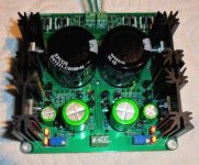
For my special needs I drew a layout of this regulator and adjusted to 200mA and +/- 15V. The operation is perfect but the small heatsinks deserve to be higher because they are relatively hot but it goes anyway.
I have not yet try this montage on my USSPA but I do not doubt the result.
Thank you Salas for this excellent project.
")
For my special needs I drew a layout of this regulator and adjusted to 200mA and +/- 15V. The operation is perfect but the small heatsinks deserve to be higher because they are relatively hot but it goes anyway.
I have not yet try this montage on my USSPA but I do not doubt the result.
Thank you Salas for this excellent project.
Attachments
Congratulations and let us know how you gonna like it. Did you also check its oscillation free by examining the rails with the scope?
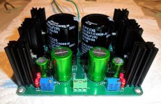
P.S. Nichicon ES is 85C type. Better use 105C C3 because you located it next to M2 so it will be receiving more radiated heat than in the regular board. Unless you measure manageable temperature on its body for your application. Every 10C less than rated, electrolytics stated lifetime doubles.
P.S. Nichicon ES is 85C type. Better use 105C C3 because you located it next to M2 so it will be receiving more radiated heat than in the regular board. Unless you measure manageable temperature on its body for your application. Every 10C less than rated, electrolytics stated lifetime doubles.
I finished this assembly today and for the moment I just check and adjust the output voltage which is very stable to the multimeter and very accurate but as it is late I will take measurements on my old oscilloscope and tests of listen in the next few days.
Yes I found once mounted for C3 and I will find a capacitor at a higher temperature and also change my layout a bit.
I will return to give my impressions
Yes I found once mounted for C3 and I will find a capacitor at a higher temperature and also change my layout a bit.
I will return to give my impressions
If it will have problem with the 100uF/50V FM there are also the 56uF/50V FM and the 68uF/35V FM that seem more in ESR range.
https://industrial.panasonic.com/cdbs/www-data/pdf/RDF0000/ABA0000C1018.pdf
https://industrial.panasonic.com/cdbs/www-data/pdf/RDF0000/ABA0000C1018.pdf
- Home
- Amplifiers
- Power Supplies
- Salas SSLV1.3 UltraBiB shunt regulator