After looking at the picture on the opening post , I would be highly suspicious of the isolation rating of that transformer inside the SMPS . If the insulation breaks down , it will be an almighty mess
Don't take chances with cheap junk , you get what you pay for
316a
...another opinion or can you back it up? Any measurement? Meltdowns?
Not asking to start a fight here - I am genuinely interested if anybody have anything solid. Other than opinions based on a picture and the"made in china" stamp.
I would be a bit more forthrite - if you haven't used the item, and haven't technically assessed it, then any opinion is just waffle and not worth reading imho.
Comments about how it performs are certainly useful, but without a technical assessment then take such comments with a grain of salt, just as one would take any sales description for the item, or listing of 'specs'.
Comments about how it performs are certainly useful, but without a technical assessment then take such comments with a grain of salt, just as one would take any sales description for the item, or listing of 'specs'.
Last edited:
A high price is no guarantee for high quality ! All to often it's only marketeers plot to get junk sold. Real quality cost yes. But one have to identify a quality item to find them, and that is not something ads will help with. Knowledge and experience is the way!After looking at the picture on the opening post , I would be highly suspicious of the isolation rating of that transformer inside the SMPS . If the insulation breaks down , it will be an almighty mess
Don't take chances with cheap junk , you get what you pay for
316a
I love the idea to use DC/DC step-up converter in tube amps. Generally, DC/DC converter for audio usage (see Oleg´s headphone amp USB powered or Jan Didden´s USB converter). In my humble opinion, I think it´s possible to design/build a technically and sonically outstanding audio DC/DC converter.
But safety is mandatory: does this cheap chinese converter supplies approvations like CE (which covers EMC)? Do I know the components brands? The PCB creapage? A lot of questions without replies.
I know, if it´s cheap you can simply try or forget.
I´ve using successfully RECOM (chinese remanufacturing) step-up converter (210V@5W)for a parafeed headphone amplifier, exactly knowing used components and defined filter.
My next parafeed hedphone amplifier build (in progress) is using the showned millett based DC/DC step-up converter (250V@10W); I´m also finishing a 6P1 headphone amplifier using a GAIA DC/DC converter powered by Lithium batteries (showned here Oleg´s thread).
Do you´ve a ebay link, I´ll buy this converter and reports measurements.
JP
Attachments
...another opinion or can you back it up? Any measurement? Meltdowns?
Not asking to start a fight here - I am genuinely interested if anybody have anything solid. Other than opinions based on a picture and the"made in china" stamp.
I am not a fan of these Ebay doo-dads....
I don't see a CE mark or any other markings identifying this complies to any safety standards or compliance with regards to RFI/EMI . What lets these cheap grey goods SMPS down is usually the transformer . I've been driven nuts trying to repair similar SMPS before , only to discover shorts within the transformer due to thinly insulated wire that was kinked or insulation breakdown between primary and secondary or feedback winding .
If these devices absolutely must be used , at least replace the capacitors with decent quality types
") I suppose with careful layout these could be reliable but for me I don't want these anywhere near my shrine to Lee DeForest
I suppose with careful layout these could be reliable but for me I don't want these anywhere near my shrine to Lee DeForest316a
Some posters incorrectly think this item isolates output voltage from input DC.
Some incorrectly imho think it should have a CE compliance cert of some kind.
It is what it is, a non-isolated step up DC/DC. Practical use is to power it from a DC heater supply - dead simple.
Some incorrectly imho think it should have a CE compliance cert of some kind.
It is what it is, a non-isolated step up DC/DC. Practical use is to power it from a DC heater supply - dead simple.
...another opinion or can you back it up? Any measurement? Meltdowns?
Not asking to start a fight here - I am genuinely interested if anybody have anything solid. Other than opinions based on a picture and the"made in china" stamp.
I've used all three mentioned in this post with good results. Furthermore the simplicity of using a 12V supply to run it is just nice.
I've built a phono/headphone amp that uses the one the OP spoke of for the headphones (280V, 65ma) and the little adjustable one for the phono (335V, 25ma) using 8 tubes all powered from a 12V 10A "laptop" style power supply with the heaters run in series pairs.
Some posters incorrectly think this item isolates output voltage from input DC.
Some incorrectly imho think it should have a CE compliance cert of some kind.
It is what it is, a non-isolated step up DC/DC. Practical use is to power it from a DC heater supply - dead simple.
Actually the one the OP wrote about IS isolated (I've just metered it), as is the jumper based one that I posted about. Still 99% of the time the input ground is tied to output ground anyway.
There is a small flood of switching mode boost converter boards on sale on China web stores lately. Today I was seeking something better than the one listed on the first post, and my attention was catched by a new board. It seems to be built better than the average and is very useful for compact builds, because it does have both a filament and a b+ supply. The best description I've found is on this Taobao seller page: 胆机 前级 电子管 DC12V升压 逆变 电路板-淘宝网全球站 It is a dual output non-insulated SMPS with 12V DC input. The first output is an adjustable 3A step-down for filaments, based on LM2575 TI SimpleSwitcher. The second output is a step-up 150-420V adjustable output with unknown power ratings. The power MOS is mounted on a relatively big heatsync, and the toroidal choke seems good enough for 100-200mA. The Taobao seller declares that it is does not produces audible noise on the tube amplifier output due to high frequency switching. Unfortunately, I was unable to trace it on more western-friendly web sites yet so I will continue to search for a seller that will at least have a web site in English.
The number of small tube amp with SMPS power supplies is also increasing. A popular cheap one, sold by doukmall and many others, is a "6N8P Tube Preamplifier for car audio". It is a existing low-voltage board design, with the addition of a new SMPS daughterboard hastly bolted on top. This board is based on the venerable TL494 PWM controllar and it does boost the b+ to 250V. The transformer core seems to be a 10-20W part, but most TL494 designs have a fixed switching frequency between 25 and 50 KHz, so I am very suspicious about the leakage on audio spectrum.
The number of small tube amp with SMPS power supplies is also increasing. A popular cheap one, sold by doukmall and many others, is a "6N8P Tube Preamplifier for car audio". It is a existing low-voltage board design, with the addition of a new SMPS daughterboard hastly bolted on top. This board is based on the venerable TL494 PWM controllar and it does boost the b+ to 250V. The transformer core seems to be a 10-20W part, but most TL494 designs have a fixed switching frequency between 25 and 50 KHz, so I am very suspicious about the leakage on audio spectrum.
I did a translate page from the link pcan provided and a word search on eBay. This is what I found:DC 12V to 150V-420V PSU Board f Amp Preamp Electronic Inverter Tube Power Module | eBay. Looks similar going to get one and check it out. Any comments?
Good for about 10W in a hot chassis by the look of it. Also more expensive than the 150W isolated one I posted before, but adjustable rather than preset voltages.
Also RE: leakage of HF switching hash: My configuration (filtered as if it was 60Hz) has no measurable noise in the audio path (measured with a scope).
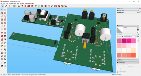
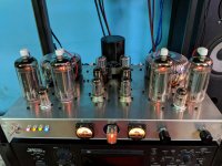
This amp I've recently completed uses boost modules from a 12V ATX 750W 80Plus gold supply (EVGA Supernova G2)
It's using 6P45S running about 300V B+ @120ma per tube (triode connection), a pair of 6N8S as a buffer with active load, and 6N1P (picture shows 6CG7 but I wanted more gain) /6N6P in an Aikido-esque config. Also the Nixie, of course.
Also RE: leakage of HF switching hash: My configuration (filtered as if it was 60Hz) has no measurable noise in the audio path (measured with a scope).
This amp I've recently completed uses boost modules from a 12V ATX 750W 80Plus gold supply (EVGA Supernova G2)
It's using 6P45S running about 300V B+ @120ma per tube (triode connection), a pair of 6N8S as a buffer with active load, and 6N1P (picture shows 6CG7 but I wanted more gain) /6N6P in an Aikido-esque config. Also the Nixie, of course.
Attachments
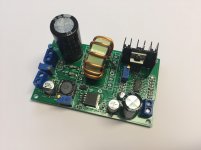
My 12V to 150-420Vdc boost, plus to 6.3Vdc buck module just came in. Nice pcb layout for the 12V to 6.3V buck converter.
Layout for the 12V to B+ boost is more of a layout compromise, and switching frequency appears low - it may take a few days to get some waveforms. The high step up ratio of the boost would support the B+ 60mA output spec limit, but for preamp applications that really is a non-issue.
Comments on module are:
12V to 150-420V boost, non-isolated (common negative 0V);
1,000uF 35V 105C.
15T on 27mmOD 14mmID toroid (likely micrometals T106-52 with AL=95, so 21uH).
IRF840 on drain connected h/s.
2x BYV26C in parallel (600V 1A 30ns).
100uF 450V Samxon 105C (KM series, 35x18mm, 490mA ripple 120Hz).
TL494C (10k RT, 10nF CT, f~12kHz).
12V to 6.3V step down, non-isolated (common negative 0V):
220uF 35V solid; LM2576S-ADJ; SS34; 470uH; 470uF 16V solid; 20k pot; 0.1uF smd on 12V and 6.3V rails.
LM2576 direct soldered to pcb with ground plane.
Cycle by cycle current limiting; 52kHz, down to 11kHz in overload with output voltage limiting to 40%; so should be fine for heater warm up.
45V max input, so cap voltage limited.
About 80% effy for heat dissipation (6.3V 1A output causes about 1.5W loss into pcb).
No input polarity protection.
Easy to add smt caps on rear of pcb for high frequency decoupling as close as possible to specific nodes.
Note that the FET heatsink is hot, in more ways than one!
Last edited:
But why take a risk, if something goes wrong you can have more than 600/700 V and you got a big mess in your amp, I can understand use it in cheap pre-amp not otherwise, I am using some of this 35VA Double 220V Double 6.3V Oxygen Free Copper Transformer 35W R type Audio Tube Preamplifier Transformer-in Amplifier from Consumer Electronics on Aliexpress.com | Alibaba Group , they are not expensive and work very well, in the other side Edcor produce a very good line of transformer for any kind of application, so why take a risk, I much prefer stay with a proper well designed power supply.
I also received the board. I ordered two of them, as I am used to do with this kind of bargain parts. Easier to spot any issues by comparing the boards. I will check them througly later on, but first impression is good. SMD parts have been manually soldered, it seems to be a early run or a very small production. The board is easy to repair because it only uses clearly marked and broadly available components, and the circuit appears to be straight from databook. This is important, because I don't want to incorporate in my amplifiers a part that will be difficult to source or repair when it fails. There is no input or output EMI filtering: the board will work anyway, but some EMI filtering must be added to comply to EU regulation, and also to avoid obliterating the AM radio reception to the neighbours, like many unbranded LED lamps do. The smt caps mentioned by trobbins are a easy and effective first step. One board came with the Samxon 450V 100uF capacitor, the other one with a Chongx 120uF 450V capacitor. This capacitor is one of the most expensive parts on the board and they clearly put there any leftover they had on the drawer from the assembly of consumer electronics SMPS. At work I replaced dozens of dried up capacitors of this exact same kind and brand from TV sets that were still on manufacturer warranty. I will exchange the capacitor with a low-ESR 450V 47uF Panasonic. It is, incidentally, about the same size of the original 100uF one and I believe that 47uF is the correct value for this circuit. Another 47uF capacitor may be eventually added after a smoothing inductance of a few mH. The 1000uF 35V capacitor is on the input side and I will probably replace it as well. Other components seems to be OK. The heatsink is small, maybe too small when you draw the maximum power. I will check this later. There is enough space for a bigger one.
To kissabout2002: on this tried and tested switching power supply design the most common failure mode is not the output that slams to the upper voltage limit, like some linear old style power supplies do. According to my experience, it mostly fails by shutting down, either because the capacitor is faulty or because the output MOS is shorted. In this case, the TL494 is usually fried too.
To kissabout2002: on this tried and tested switching power supply design the most common failure mode is not the output that slams to the upper voltage limit, like some linear old style power supplies do. According to my experience, it mostly fails by shutting down, either because the capacitor is faulty or because the output MOS is shorted. In this case, the TL494 is usually fried too.
Attachments
Last edited:
Compliance would depend on the total system, not just this pcb, so whether extra filtering is needed would be an open issue. This pcb operates from dc input and would likely be contained in a metal chassis, unlike LED lamps that I think you are referring to, so it could be an apples and oranges comparison.There is no input or output EMI filtering: the board will work anyway, but some EMI filtering must be added to comply to EU regulation, and also to avoid obliterating the AM radio reception to the neighbours, like many unbranded LED lamps do.
I wouldn't think that many DIYers would need to consider changing parts in the pcb - maybe you are aiming to use this pcb in a commercial amp product where service life and equipment failure have consequences back on you.At work I replaced dozens of dried up capacitors of this exact same kind and brand from TV sets that were still on manufacturer warranty. I will exchange the capacitor with a low-ESR 450V 47uF Panasonic. ..... The 1000uF 35V capacitor is on the input side and I will probably replace it as well.
Guys first I do not want offend anybody also I do not want doubt that this step up converter are not good, I am not an electronic engineer just a technician with lot of experience on the field, I start fixing electronics back in Italy on the 1972, a that time just television set with tubes, then appear the transistors and CI and all manufacturer start using the new available technology so very surprise I remember open a first Telefunken colour tv with no tubes and no power transformer, with this new switching power supply, was a wow, I think was around 1980, well not sure, but anyway all was so great but then when lots of this television set was on the market also realise the down term of this kind of power supply when the grid get messy like during a thunder storm with lots of lighting, well when finish the telephone of my laboratory was keep ringing client call me for fix their televisions, well of course was good money making but in the other side I realise how fragile this power supply could be, and I saw so many television being completely ruing by the switching power supply.That of course happened because back in Italy a that time power grid and transformers was mounted on post on open field so very exposed to lighting, nowadays many country like in Ireland where I lived all has been moved under ground so less expose to this kind of problem, still here where I live now in Philippines still same problem and 2 of my LCD tv gone dead after a strike lightning, I know somebody can say the switching used on television set are different but the principle is the same. Therefore, and this is just my opinion, I will never use one of them on a tube amp, I am building different tube project but anyway I will give a try to use maybe one of them is some simple tube pre-amp I will see…..in the main time best regards to everybody.
They step up from 12V. When was the last time you had a lightning strike kill your (good quality) ATX computer power supply? If you're really worried about it you could power it from a 12V transformer supply instead or even a car battery.
On a side note, I got a power meter today. My 12V ATX powering 3 boost converters for HV in my tube integrated amp draws 20% less power, and a better power factor than a similar amp I built with passive supply.
On a side note, I got a power meter today. My 12V ATX powering 3 boost converters for HV in my tube integrated amp draws 20% less power, and a better power factor than a similar amp I built with passive supply.
- Status
- This old topic is closed. If you want to reopen this topic, contact a moderator using the "Report Post" button.
- Home
- Amplifiers
- Power Supplies
- High Voltage Boost Converter - sacrilege?