I choose not to stoop to your level by returning your unnecessary sarcastic insults.
your memory is fading fast. I seem to recall you said I was an 'idiot' when I pointed out your design failed to meet the power efficiency of the lowly Astron. I'm done here
folks that start changing to OffTopic when their lil' brains implode.
Last edited:
your memory is fading fast. I seem to recall you said I was an 'idiot' when I pointed out your design failed to meet the power efficiency of the lowly Astron.
What next? You're on a roll....
60A x 20V = 1200 watts. My estimate of 1160 watts was close enough.
Yes the numbers are coincidentally close, if you don't care what the question was. 1200 W is total DC power input. Was it the question you answered to? Not.
You're getting a little bit too comfortable with the condescension; borderline insulting. Look, I get it... you're trying to 'teach me a lesson' because clearly I'm not an electrical engineer.
No. Because I want to be productive. Im sorry for helping. Knowing these rules doesn't need to be an engineer, I learned them in secondary school. But designing a good PSU requires this knowledge, and you stated this is your goal.
Im so not comfortable with condescension, that I even don't know what it means. ;-) But this is not a psychology forum, and my task is not to protect your self-esteem.
Does berating me make you feel good about yourself?
No. Having to repeat the same thing without any acknowledge not either.
The chassis heat sink specification = 38 C°/W. That's a great starting place for this build.
If that was true, then you had no chance to build a 8 A PSU in it. Make calculations!
Sure, I'll have some level of decreased heat sink efficiency due to the mounting solution for the TO-3 packaged devices, but with the selected Fan and chassis design, I still feel confident it's 'good enough' to proceed with building a prototype and getting real-world test results.
Anything is enough for a test. I warned you, now you can do whatever you want.
The system design must also be easy to troubleshoot and repair. Many industrial designs place much less emphasis on that criteria, because they are building to a price point. They have to calculate the very smallest of details, in order to develop a BOM at the lowest possible cost (...lowest quality) to barely get by with a product that will last long enough to surpass the warranty period.
Good day Sir. I think it's safe to say that this thread has run its course, at least from my perspective.
You haven't helped yet, but I do anxiously wait for it. Here's your chance.No. Because I want to be productive. Im sorry for helping.
I didn't post here so that you can 'feel productive' at my personal expense. Let's try a different approach; how about you, for a change, actually demonstrate your vast knowledge that you learned in secondary school.
Instead of simply stating that my thermal mgmt / cooling design is junk, enlighten all of us; show us some, any, empirical data / equations that gives you such great confidence trashing the prototype design. All you've stated is opinion without evidence, yet you demand that I produce evidence for you. Aren't you supposed to be the mentor in this case? Show us what a great mentor you can be. Prove that this cooling / thermal strategy is less than adequate and I'll listen.
.also chose NOT to share mathematically why he felt is was so inadequate
Flow engineering is extremely complicated, basically everybody make measurement to validate a specific arrangement. To do this is naturally not my task. But Ive designed and built many power device to estimate more or less correctly. You, since don't care about dissipation numerically cant tell what is good. You confused output power with dissipation, that is the main source of your bad decision. Also you dont understand the main working principles of cooling.
.
Flow engineering is extremely complicated, basically everybody make measurement to validate a specific arrangement. To do this is naturally not my task. But Ive designed and built many power device to estimate more or less correctly. You, since don't care about dissipation numerically cant tell what is good. You confused output power with dissipation, that is the main source of your bad decision. Also you dont understand the main working principles of cooling.
Of course I don't, I'm not an engineer. I don't need to be an engineer to know that air will flow in this chassis to an extent GREATER than air flows in any desktop Astron power supply. That's all I need know, because I've designed the chassis fan installation such that it can be easily updated if needed after a few measurements are taken when it is on the test bench.
Once again, you offer 'nothing' productive to this conversation. Have a good day Sir. You're wasting my time.
A few things, in case the OP has subscribed to his thread.
First, I am a ham radio operator, and while I do like to not spend excessive money for anything I also do not and have never built anything that is not reasonably aesthetically good, and (except for errors) nothing that fails to fulfill its intended function. Fwiw, my first rig was a copy of a 6146 transmitter from the 1965 ARRL handbook, and still looks pretty ok today. I was 14 at the time. Knew next to nothing with a freshly minted novice license.
So, I'd suggest that your characterization of "hams" as a generalization is not one that applies, it probably does apply to a segment of the ham operators.
Ok, thermal considerations? Wakefield and other heatsink mfrs have extensive design information on their sites. They have graphs, so you don't need higher math to get "in the ballpark". It is a good idea to look at what professional manufacturers have done, since their products do in fact need to be reliable, or else they will lose their "shirts" and a lot of money.
Not sure why you would use 11 devices, when you can use 12?? Did I read that correctly?
Pictures and diagrams of your proposed design or the actual parts would not hurt the project.
(EDIT: I looked back and you did provide some...)
There is a freeware I think from Duncan called PSUD which is a power supply design software. Personally I don't think it is so great to use, but it will give you some valuable information back.
The advice given is likely of value to your build - the manner in which it was delivered may not be a "collegial" as one may wish for, but it doesn't change its value (high or low value) and ought to be considered free of anyone's "style".
I do think that more explanation regarding some of these issues is and would be of value, since not all that come here or read these threads are "up to speed" in terms of theory or practice. If not explanation, then links (which some did) are of help...
_-_-
Last edited:
Heatsink design...
Blown heatsinks have limits as to how much air can be blown and still be effective... the heatsinks you showed unless they are set up so that they are in a "tunnel" or have equivalent means to push the air through will have somewhat limited thermal capability.
You'd want to work backwards from how much current & voltage worst case each of the devices will have running through them, and then figure out the watts and so the expected temperature rise. That will tell you what you need for heatsinks.
It's not unreasonable to do an empirical test by taking a single TO-3, mounting it to one of your brackets, and then using a test circuit running it up to the same power level, connected to a heatsink and then using a non-contact thermometer (Harbor Freight sells 'em cheap) to see the temp rise on the case, the bracket and the heatsink. This will tell you pretty quick if you have enough thermal path via the bracket, and then TO the heatsink. Keep in mind that if you do not shorten the bracket, the results will be much better than you will get with two devices (or more) contributing to the heat...
You will need a very flat surface between the bracket and the heatsink to get good thermal conductivity, and a means to maintain that contact. The higher the temp rise, the more important that becomes. But again, you can test it empirically and then make corrections and changes to the design.
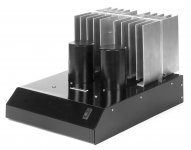
Attached is a image of one of my (now old) DC coupled SE Mosfet amps - of note is the heatsink. The amp runs ~35watts OUT, but about 3-4x that in HEAT. The heatsink is made of a single 7/16" thick aluminum plate, and THEN the larger than possible with extrusion fins were added. This is adequate for natural convection at this power level, using 6 devices total. The key to its success as a heatsink is the single 7/16" plate as it has no thermal breaks between the device and it, so the heat is evenly spread first, before it goes to the added-on fins. This keeps the temp rise in the devices minimized and stable.
_-_-
Blown heatsinks have limits as to how much air can be blown and still be effective... the heatsinks you showed unless they are set up so that they are in a "tunnel" or have equivalent means to push the air through will have somewhat limited thermal capability.
You'd want to work backwards from how much current & voltage worst case each of the devices will have running through them, and then figure out the watts and so the expected temperature rise. That will tell you what you need for heatsinks.
It's not unreasonable to do an empirical test by taking a single TO-3, mounting it to one of your brackets, and then using a test circuit running it up to the same power level, connected to a heatsink and then using a non-contact thermometer (Harbor Freight sells 'em cheap) to see the temp rise on the case, the bracket and the heatsink. This will tell you pretty quick if you have enough thermal path via the bracket, and then TO the heatsink. Keep in mind that if you do not shorten the bracket, the results will be much better than you will get with two devices (or more) contributing to the heat...
You will need a very flat surface between the bracket and the heatsink to get good thermal conductivity, and a means to maintain that contact. The higher the temp rise, the more important that becomes. But again, you can test it empirically and then make corrections and changes to the design.
Attached is a image of one of my (now old) DC coupled SE Mosfet amps - of note is the heatsink. The amp runs ~35watts OUT, but about 3-4x that in HEAT. The heatsink is made of a single 7/16" thick aluminum plate, and THEN the larger than possible with extrusion fins were added. This is adequate for natural convection at this power level, using 6 devices total. The key to its success as a heatsink is the single 7/16" plate as it has no thermal breaks between the device and it, so the heat is evenly spread first, before it goes to the added-on fins. This keeps the temp rise in the devices minimized and stable.
_-_-
Attachments
Last edited:
Hi Bear, thanks for the follow-up. My generalization was in response to a previous poster that generalized ham operators incorrectly. So I responded with a correction. He stated that I'm not like most hams, to which I agreed, in that I don't mind spending money to build a great power supply, both functionally and aesthetically. Unlike most ham operators, I did not want money to be a design constraint in any way for this ambitious project. That puts me into the minority of ham operators. That's all I was trying to convey.A few things, in case the OP has subscribed to his thread. I'd suggest that your characterization of "hams" as a generalization is not one that applies, it probably does apply to a segment of the ham operators.
I agree 100%. I used the Astron VS-70M heat sink design as a starting point. Their supply is 70 amps. My design is 80 amps, but at higher duty cycle. So in order to get a prototype built so that I can take real-world design measurements, I've started with close to double the sink size and better fan cooling. That should get me close, which saves time and money by not having to manufacture one-off sink panels for the chassis that I've selected. I've selected a stronger fan with much better chassis airflow over the Astron chassis and fan design. There are many aspects of the Astron design that is sub-par / barely meets minimal specs, etc. Although, I do give Astron credit for the way they wired the power points within the chassis for minimal losses. I'm designing for an order of magnitude improvement over the Astron... which as you can imagine, increases the price significantly but that's ok by me....(heat sinks) It is a good idea to look at what professional manufacturers have done, since their products do in fact need to be reliable, or else they will lose their "shirts" and a lot of money.
I'm using 10 pass transistors, with 1 drive pass transistor (with darlington feeders to keep the LM723 happy). That's why the total count of the 2N5686 is 11. Each of the 10 output transistors will provide 8 amps at maximum output power of 80 amps, which is cruising along without breaking a sweat, since they theoretically can provide up to 50 amps each. I'm no longer considering an internal bracket design for the pass transistors. Now the design is to mount them directly onto the heat sink side panels. It will cost me a few hundred dollars to have the side panels milled out with channels for the pass transistors, but it's a worthwhile design change for the sake of dissipation efficiency in the long run.Not sure why you would use 11 devices, when you can use 12?? Did I read that correctly?
Thanks for the link Bear, I'll check it out.There is a freeware I think from Duncan called PSUD which is a power supply design software. Personally I don't think it is so great to use, but it will give you some valuable information back.
I agree. Although there were a couple of very helpful tid-bits in the mess of condescending responses received, I found the overall experience quite disappointing. Thanks for your response; much appreciated.I do think that more explanation regarding some of these issues is and would be of value, since not all that come here or read these threads are "up to speed" in terms of theory or practice. If not explanation, then links (which some did) are of help...
Well, as I said try to ignore the tone that some posters appear to regularly put forth. Focus on the information.
The thing I said originally, if that IF you have a stiffer *source* meaning AC mains line, and larger iron to back it up, THEN you can drop less volts across your "regulator" which means LESS HEAT and lower losses.
You can do this, ASTRON and the like can not on a commercial basis.
There is zero reason to have to spend hundreds of dollars on heatsinking, imo.
None that I can come up with.
You'll want to consider various options, including surplus gear that already has devices mounted for "blown cooling". I expect you have seen gear made with those heatsinks that alone in cross-section look like a "christmas tree" but are used in fours to form a
box/tunnel with a fan at one end?? Best bet for an application like this...
There's nothing wrong with the angle mount approach - it's just that you want to take into account, either by computation OR by empirical experiment the temperature rise/power dissipated by the device vs. the ability of the aluminum to carry that heat away and couple it to the outside world...
Fwiw, the 1 pass transistor that drives the rest is not likely to use up much power, so does not need the same heatsinking...
Also the total dissipation for your pass transistors is not merely the current drawn, you want to take into account the voltage dropped across them, that being the B+ voltage vs. the regulated voltage. Likely these devices are sufficient, but we're talking about getting rid of heat...
Perahps someone reading would like to suggest a more "modern" chip or circuit that might be considered?? I think there were some comments as to the age of these 723s?
- Status
- This old topic is closed. If you want to reopen this topic, contact a moderator using the "Report Post" button.
- Home
- Amplifiers
- Power Supplies
- 13.8V 80A Linear PS circuit design analysis for Ham Radio Use