2022 JUNE 09 -- SOLD OUT (YOU CAN STILL SEND THE GERBERS TO A PCB FAB AND BUY BOARDS YOURSELF)
2022 JUNE 09 -- SOLD OUT (YOU CAN STILL SEND THE GERBERS TO A PCB FAB AND BUY BOARDS YOURSELF)
Transformer schematics include "Phase Dots" that indicate which ends of the windings are in phase. Unfortunately, many transformers in used equipment are not marked with phase dots, and quite a few new transformers are not marked either.
If you have a signal generator and an oscilloscope, it's easy to determine the phase dots: see the first picture. If scope channel2 is "right side up" compared to channel1 then winding2 is in phase with winding1, and "?" becomes a dot. And vice versa. However, some DIYers don't have a signal generator and a scope, so this little tester board called "PhaseDots" might help.
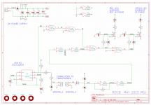
It operates on the same principle, but instead of a scope and human eyeballs, the circuit uses a phase detector (XOR gate) to decide whether the windings are in phase or out of phase. This lights up either a Green LED (in phase) or a Red LED (out of phase). Simple and unambiguous. The circuit schematic is picture#2.
A 555 timer/oscillator drives a square wave into transformer winding#1. The resulting waveform on winding#2 is amplified in a series of CMOS logic inverters (gain > 5x per stage) and compared in XOR gate U1C. If they're in phase, D4 lights up. If not, D3 lights up. RC pulse shapers with slow risetime and fast falltime, drive the LEDs.
In practice the tester board is simple to use. Connect one of the transformer's primary windings to connector P2 (labeled WINDING_1) and leave it connected. Then, one by one, connect all the other windings to connector P3 (labeled WINDING_2) and observe their dots. Write these on a schematic as you go. After the last winding: Boom, you're done!
It is important that the PhaseDots tester should always drive a transformer primary winding. (I.e. always connect a primary winding to WINDING_1). Why? Because transformer primary windings have sufficiently high self-inductance to ensure a long (L/R) timeconstant. This prevents the winding from behaving as a differentiator, ruining the input waveform and lighting up the wrong LED (or both LEDs).
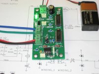
Picture 3 attached, shows the PhaseDots tester connected to an Antek AS-2222 toroidal transformer. Red and black are a primary winding, blue and green are a secondary winding. The illuminated green LED tells us that if red has a Phase Dot, then so does blue.
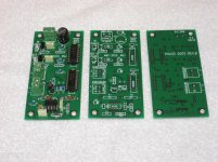
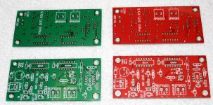
A few other pictures are attached, showing the PCB that I laid out. There's also a set of Gerber files that anyone can send to a PCB fab (I recommend PCBshopper.com to help you choose a fab) and have their own boards made. The Gerber files are included in a zip archive, along with a Bill Of Materials and other ancillary stuff.
I built several PhaseDots boards for my own use, but I've got some leftover boards and leftover kits of parts which I am willing to let other DIY hobbyists have at my cost.
Sorry, I will not accept PayPal. I will not accept wire transfers. I will not accept Western Union. If you want to set up a little re-distributorship that does accept these, so you can forward boards and kits to other DIYers, please go right ahead with my blessings and good wishes.
Anybody who wants a board or a board + kit of all parts, send me a Private Message ("send me a PM") for purchasing information, mailing address, etc. I've got approximately twenty of them to get rid of.
Hope you enjoy the PhaseDots tester!
2022 JUNE 09 -- SOLD OUT (YOU CAN STILL SEND THE GERBERS TO A PCB FAB AND BUY BOARDS YOURSELF)
2022 JUNE 09 -- SOLD OUT (YOU CAN STILL SEND THE GERBERS TO A PCB FAB AND BUY BOARDS YOURSELF)
2022 JUNE 09 -- SOLD OUT (YOU CAN STILL SEND THE GERBERS TO A PCB FAB AND BUY BOARDS YOURSELF)
Transformer schematics include "Phase Dots" that indicate which ends of the windings are in phase. Unfortunately, many transformers in used equipment are not marked with phase dots, and quite a few new transformers are not marked either.
If you have a signal generator and an oscilloscope, it's easy to determine the phase dots: see the first picture. If scope channel2 is "right side up" compared to channel1 then winding2 is in phase with winding1, and "?" becomes a dot. And vice versa. However, some DIYers don't have a signal generator and a scope, so this little tester board called "PhaseDots" might help.
It operates on the same principle, but instead of a scope and human eyeballs, the circuit uses a phase detector (XOR gate) to decide whether the windings are in phase or out of phase. This lights up either a Green LED (in phase) or a Red LED (out of phase). Simple and unambiguous. The circuit schematic is picture#2.
A 555 timer/oscillator drives a square wave into transformer winding#1. The resulting waveform on winding#2 is amplified in a series of CMOS logic inverters (gain > 5x per stage) and compared in XOR gate U1C. If they're in phase, D4 lights up. If not, D3 lights up. RC pulse shapers with slow risetime and fast falltime, drive the LEDs.
In practice the tester board is simple to use. Connect one of the transformer's primary windings to connector P2 (labeled WINDING_1) and leave it connected. Then, one by one, connect all the other windings to connector P3 (labeled WINDING_2) and observe their dots. Write these on a schematic as you go. After the last winding: Boom, you're done!
It is important that the PhaseDots tester should always drive a transformer primary winding. (I.e. always connect a primary winding to WINDING_1). Why? Because transformer primary windings have sufficiently high self-inductance to ensure a long (L/R) timeconstant. This prevents the winding from behaving as a differentiator, ruining the input waveform and lighting up the wrong LED (or both LEDs).
Picture 3 attached, shows the PhaseDots tester connected to an Antek AS-2222 toroidal transformer. Red and black are a primary winding, blue and green are a secondary winding. The illuminated green LED tells us that if red has a Phase Dot, then so does blue.
A few other pictures are attached, showing the PCB that I laid out. There's also a set of Gerber files that anyone can send to a PCB fab (I recommend PCBshopper.com to help you choose a fab) and have their own boards made. The Gerber files are included in a zip archive, along with a Bill Of Materials and other ancillary stuff.
I built several PhaseDots boards for my own use, but I've got some leftover boards and leftover kits of parts which I am willing to let other DIY hobbyists have at my cost.
PCB only: {$6 ship to USA} {$9 ship to CAN+MEX} {$12 ship to rest of world}
PCB + kit of all parts: {$13 ship to USA} {$16 ship to CAN+MEX} {$22 ship to rest of world}
However, I will only accept cash or checks. Fortunately I will accept a check drawn on a non-USA-bank and denominated in non-USA-currency.Sorry, I will not accept PayPal. I will not accept wire transfers. I will not accept Western Union. If you want to set up a little re-distributorship that does accept these, so you can forward boards and kits to other DIYers, please go right ahead with my blessings and good wishes.
Anybody who wants a board or a board + kit of all parts, send me a Private Message ("send me a PM") for purchasing information, mailing address, etc. I've got approximately twenty of them to get rid of.
Hope you enjoy the PhaseDots tester!
2022 JUNE 09 -- SOLD OUT (YOU CAN STILL SEND THE GERBERS TO A PCB FAB AND BUY BOARDS YOURSELF)
2022 JUNE 09 -- SOLD OUT (YOU CAN STILL SEND THE GERBERS TO A PCB FAB AND BUY BOARDS YOURSELF)
Attachments
-
 PhaseDots_Principle_of_Operation.png10 KB · Views: 2,861
 -
 PhaseDots_schematic.png37.9 KB · Views: 2,776
 -
 PhaseDots_In_Operation.jpg423.4 KB · Views: 2,709
 -
 PCB_photo.jpg505.3 KB · Views: 2,484
 -
 front.png32.6 KB · Views: 2,369
 -
 back.png31.4 KB · Views: 1,094
 -
PhaseDots_Gerbers_and_Everything_Else.zip171.4 KB · Views: 559
Last edited:
I don't think I have ever seen a transformer marked with "phase dots". They are a circuit diagram convention, not a component labelling convention.
Great tool, love that you keep it open source and include the gerbers
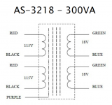
Never seen an antek transformer.. if the circuit is printed as a label on the transformer with colour/pin# to phase dot? (maybe i'm missing the joke 🙂)..
Never seen an antek transformer.. if the circuit is printed as a label on the transformer with colour/pin# to phase dot? (maybe i'm missing the joke 🙂)..
I don't think I have ever seen a transformer marked with "phase dots".
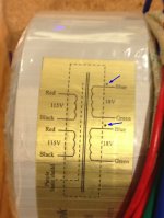
Let me introduce to the Antek AS-3218. Here is a color photo of the actual transformer itself, and a snip from the (black and white) datasheet on the manufacturer's website. Look for the blue arrows that I drew upon the photo.
Attachments
It's true that only accepting checks and currency makes the transaction convenient for me and perhaps inconvenient for buyers. Fortunately you do have several options:
_
1. Simply forget about PhaseDots. Three days ago you hadn't heard of it and you didn't want it. You were happy and contented without it. Continue on that PhaseDots-free path of life and remain blissfully satisfied & happy.
2. Have the PCB fabbed for you. Post#1 contains the Gerber files which is all you need to order some PCBs. Just now I got a quote from PCB shopper dot com (4.9cm x 9.9cm, qty=10) of $1.85 per board including shipping to the US. Then buy the parts from your local shop or distributor. (BOM is in post#1). Easy. Build one or two boards and give away or sell the others.
3. Wait until someone creates a re-distributorship, buying boards and kits of parts, then re-selling them to you. Don't laugh, it happened (twice) with Quasimodo boards. Two different diyAudio members set themselves up as vendors of Quasimodo PCBs + kits of all parts, and accepted PayPal / BitCoin / Western Union / etc as payment.
I'm selling these at my cost, with zero profit (and my cost is low because I got the quantity=50 discount). If you'd prefer to wait until somebody starts selling them for a profit, you have that right. Remind yourself how much inconvenience and risk you have avoided, and remind yourself that the extra time and extra cost are quite acceptable.2. Have the PCB fabbed for you. Post#1 contains the Gerber files which is all you need to order some PCBs. Just now I got a quote from PCB shopper dot com (4.9cm x 9.9cm, qty=10) of $1.85 per board including shipping to the US. Then buy the parts from your local shop or distributor. (BOM is in post#1). Easy. Build one or two boards and give away or sell the others.
3. Wait until someone creates a re-distributorship, buying boards and kits of parts, then re-selling them to you. Don't laugh, it happened (twice) with Quasimodo boards. Two different diyAudio members set themselves up as vendors of Quasimodo PCBs + kits of all parts, and accepted PayPal / BitCoin / Western Union / etc as payment.
_
Attachments

Last edited:
Yes and I replied just now (Tuesday 09_June , 1620 Athens time)I have sent you a PM, have you received it.
That wasn't just flippant remark meant to irritate you, i was being serious.
I always take note of windings phase, something i had to get in the habit of doing in a 240v world where i almost always have to wire primarys in series, so i make the effort to match the secondary side while i am at it, and if necessary use a scope to work it out if datasheets and wire colours dont indicate the start of each winding. I do appreciate the work you put into your projects, i made a version of your quasimodo which i use on every project now to work out snubber values, this looks like another useful tool for the toolbox.
I always take note of windings phase, something i had to get in the habit of doing in a 240v world where i almost always have to wire primarys in series, so i make the effort to match the secondary side while i am at it, and if necessary use a scope to work it out if datasheets and wire colours dont indicate the start of each winding. I do appreciate the work you put into your projects, i made a version of your quasimodo which i use on every project now to work out snubber values, this looks like another useful tool for the toolbox.
A bunch of people purchased a Quasimodo PCB + kit of all parts, using currency. Maybe one or more of them might reply to you (assuming they're still subscribed!), if you ask on the Quasimodo thread: "Why did you decide to buy with currency? Now that the transaction is completed, do you regret using currency? Overall, are you pleased with the outcome?" and so forth.
Step back all of you, a real electrician came in the village.
The all conversation is about a simple phase rotation verification.
Get this tool and enjoy.
UT15C Voltstick by UNI-T, product pictures by Kiriakos - ITTSB
The all conversation is about a simple phase rotation verification.
Get this tool and enjoy.
UT15C Voltstick by UNI-T, product pictures by Kiriakos - ITTSB
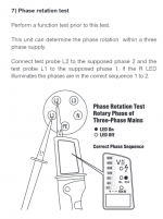
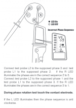
The user manual for the VoltStick is online. I screen-captured the pages that discuss its Phase Rotation Test feature. When you connect VoltStick to a three phase power distribution cable (AC mains), VoltStick tells you whether Phase1, Phase2, and Phase3 are labelled correctly.
_
_
Attachments
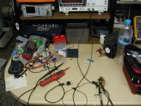
Well, boys in electronics use breadboard to play with components I did my own experiment with regular transformer by feeding it with signal generator and by using my oscilloscope too.
The Oscilloscope was used with both channels mostly for voltage confirmation.
UT-15C when used between L1 and neutral works as single phase detector.
I can tell neutral from live.
In my experiment I did feed 2V at the side of 12V transformer and from the 220V side I got about 80V as output.
By having active the test bed, I did connected UT-15C at the input of signal generator (positive) side.
By touching the other end of this tester at the output of the transformer the Green arrows was changing direction according to polarity change.
I did read and find info of your circuitry that is about measuring phase shift, at no powered transformer.
Well in my experiment I used the power it self so to show me the way. 😉
Now my opinion is that this PhaseDots / phase shift detection, does no seems crucial.
Especially when the output gets converted to DC.
Personally I can not imagine anything using plain AC other than tubes so to warm up.
Additionally any reverse placement of the power cord, it will destroy the perfect balance (if there is such a thing).
Bellow is a picture from the crime scene. 🙂
Attachments
It turns out that I will have a few unused PCBs made from red laminate. While supplies last you can choose either red or green, whichever you prefer. When I run out of one or the other color, I'll post a message here and I'll stop accepting orders for that color.
The PCB shopper dot com website lets you specify the color of the boards when you ask for a price quote, and when you order boards. Red, white, green, blue, black, yellow, and purple are available from PCB fabs.
_
The PCB shopper dot com website lets you specify the color of the boards when you ask for a price quote, and when you order boards. Red, white, green, blue, black, yellow, and purple are available from PCB fabs.
_
Attachments
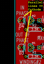
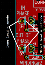
I've heard from early kit builders that the orientation of the LEDs might be a little confusing, so here is some additional information to help clarify the situation.
First of all, I apologize. The Kingbright LEDs I bought and shipped in the kits, really are confusing. Their datasheet mechanical drawing is attached below; notice that there isn't any "notch" or "flat spot" or mechanical key to help you visually determine which terminal is the anode and which terminal is the cathode (!!) The only difference you can see with the naked eye is: the cathode lead is shorter.
Fortunately we are resourceful people here at diyAudio, and so we realize that "visually" is not the only way to examine an LED. We've also got digital multimeters! If you get confused, or if you just want the extra reassurance of a double-confirmation, you can use the Diode Test feature of your DMM to tell you which end of an LED is the cathode and which end is the anode. Here are some internet resources to guide you
_
First of all, I apologize. The Kingbright LEDs I bought and shipped in the kits, really are confusing. Their datasheet mechanical drawing is attached below; notice that there isn't any "notch" or "flat spot" or mechanical key to help you visually determine which terminal is the anode and which terminal is the cathode (!!) The only difference you can see with the naked eye is: the cathode lead is shorter.
Fortunately we are resourceful people here at diyAudio, and so we realize that "visually" is not the only way to examine an LED. We've also got digital multimeters! If you get confused, or if you just want the extra reassurance of a double-confirmation, you can use the Diode Test feature of your DMM to tell you which end of an LED is the cathode and which end is the anode. Here are some internet resources to guide you
- From the website All About Circuis
- From the website Engineer's Garage
- A zillion schematics from Google Images
_
Attachments

Last edited:
You have to pay me 200$ for the tip that I gave ya which sends your circuitry to it grave.
If you plan to empty the pockets of lightweight thinking kids, by the excuse of selling them PCB, I am going to blow you out of the water.
If you plan to empty the pockets of lightweight thinking kids, by the excuse of selling them PCB, I am going to blow you out of the water.
Hey this is very useful - I have long forgotten custom toroids with multiple secondaries that I can never remember how to wire up for series/parallel as the wires are all the same color!
A whole lot bigger than your snubber rig though 😉)
A whole lot bigger than your snubber rig though 😉)
Kiriakos, thank you very much for posting your insight and wisdom here. I'm sure other members are grateful too.
Last edited:
I've heard from early kit builders that the orientation of the LEDs might be a little confusing, so here is some additional information to help clarify the situation.
First of all, I apologize. The Kingbright LEDs I bought and shipped in the kits, really are confusing. Their datasheet mechanical drawing is attached below; notice that there isn't any "notch" or "flat spot" or mechanical key to help you visually determine which terminal is the anode and which terminal is the cathode (!!) The only difference you can see with the naked eye is: the cathode lead is shorter.
Well, there is another way if the LED is clear or semi-clear. There's a cup-like structure inside the LED. I guess it's what holds the junction as the light is emitted from it.
With normal LEDs, I have always seen that this structure is connected to the kathode and it clearly takes up more space inside the LED than the anode.


Last edited:
Why you are searching for a tree and lose the forest?
Just use your digital multimeter at diode function and done. See the attached pic.
I do not agree that the gadget is useless. You can help you fast to verify primary/secondary/secondaries winding phasing which is important to Audio and RF signal transformers. I don't know if the frequency is suitable for RF transformers, though.
Attachments

Last edited:
- Home
- Amplifiers
- Power Supplies
- A little tester to determine transformer PhaseDots with no scope or signal generator