Andreas
This got me wondering, so I looked it up, here
Nelson says: «You will also note 10 uF film capacitors across the supply lines. You can delete these, remembering that the prototype used them.»
Furthermore, If you search the thread for "output snubbers", 6L6 and others say that you'd better omit these. Otoh, the input snubber seems to be if not important, than at least very beneficial. (The better the snubber is matched with your transformer's characteristics, the more good it does. See Quasimodo for this, and if you're lucky, your tranny is mentioned here)...
Thanks for the reply!
Forgot I posted that message. Maybe too many glasses of pre-Christmas wine... embarrasing post as I mistook the bleeders for something else.
That schematic is why I asked about the 10uF film cap. But it wont affect hum issues, which was my main reason for considering it, so I dropped those plans.
I decided to test the output snubber since I had the parts. Actually, doesn’t seem to have hurt anything. If anything, cleaner highs.
Wrt input snubbers, I decided to follow Waynes take on it. In a thread here he concluded, after testing input snubbers, that they might provide less ringing, but not automatically better sound. So he swears to snubberless soft recovery rectifiers, if I remember correctly. So if I build a new one, that’s what I will test as I have fast recovery ones now. I know this is a touchy subject, and tbh, I am open to changing that stance. It is not based on better knowledge than anyone. Until I read those posts, I had them in my Mouser basket but deleted. I think it was Mark Johnson who really did a lot of testing of input snubbers, and I believe his article was published in Jan Diddens magazine.
Btw my tranny is not in the quasimodo thread, allready checked. So without the kig probably just as well I dropped it.
I am considering ordering a few 35v/200s for testing, they are cheap. Nelson used to use a cap across these «to make them slower». Anyone know the type or value? Does not look like he uses the caps anymore in FW, though, or does he?
Pass Labs apparently use the soft recovery ones as Wayne likes them, according to a thread I read but can’t find right now.
Last edited:
F4 is an incredible amp. Sounds only like what’s driving it.
You have both the F4 and the BA-3. The BA-3 complimentary OS is more or less rhe same as in the F-4, if I am not mistaken. How would you compare the two? Of course the BA-2 will be affected by choice of FE, but still, I am curious. As always.
Well, the output stage of BA-3 is identical to an F4, so then it goes to say that the BA-3 sounds like it’s front-end.
Which is very similar to a scaled-down, no-feedback F5...
The BA-3 sounds like everything I like about the F5 with nothing I dislike. If I had to choose only one of these amps, it would probably be the BA-3.
F4, as mentioned before, sounds like whatever is driving it. It has essentially no sound of its own. Drive it with a small single-ended tube amp and it will sound exactly like that amp. (Except that it will actually be able to make bass... the advantages of low output impedance and the ability to move real current)
F4
This is what I'm looking forward to. I have two pre-amps that I seldom use (NAD C165BEE and Superphon Revelation II) because my DAC can feed directly to my tube amp (Golden Tube SE-40). Now, I'll flip that around and listen to my pre-amps.F4 is an incredible amp. Sounds only like what’s driving it.
@6L6, do you know if there's a place where I can learn more about the F-4 design? I'm guessing that it's clear for a EE, but that isn't me. I'll dig around and learn what the various parts do, but anything that speeds the process is welcome. Thanks for your help so far, and any pointers.
There's this FIRST WATT and this A guide to building the Pass F4 amplifier. but 6L6 may have more info still
@6L6, do you know if there's a place where I can learn more about the F-4 design? I'm guessing that it's clear for a EE, but that isn't me. I'll dig around and learn what the various parts do, but anything that speeds the process is welcome. Thanks for your help so far, and any pointers.
I think you’ll find that no feedback preserves the organity of the music in a quite different way than many other designs. And the positive phase 2. harmonic of the IRF’s will provide some warmth too. See 6L6s listening inpressions upon first power-up, and possibly some 3rd harmonic at full output.
Beware, take your time biasing and adjusting offset. No feedback means patience is in order, at least in the case of BA-3. By this I mean let the amp reach full thermal equilibrium, preferably with the amp positioned in it’s final home position, before making final adjustments. I say this without knowing exactly how Nelson provided «correction» in the F4, but at least in the case of BA-3, time and time and patience is very rewarding.
 Edit: I did not mean 6L6 will provide the 3rd harmonic. The amp will, I believe
Power Supply 18 or 20V DC (3A)
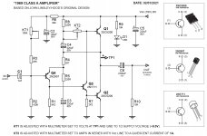
Hello guys, my name is Tiago Sierra, I'm from Brazil. I'm building a JLH 1969 10W amplifier (19V DC).
I'm using a 19.43V DC (3A) notebook power supply to connect the amplifier. But I would like to make my own source, to improve the performance of the amplifier and keep the signal cleaner. Does anyone have any circuit diagram? I need to connect 220V AC to 18 or 20V DC (3A). Thanks.
Attached is the amplifier circuit I'm using.
Attachments
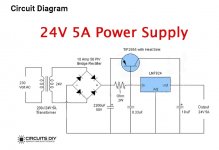
power supply 24V DC (5A)
Hello guys, I found this circuit on the internet. Would it be ideal for an audio amplifier? Or do you need more components to better filter the voltage? thanks.
24 Volt 5 Ampere Power Supply Circuit
Hello guys, I found this circuit on the internet. Would it be ideal for an audio amplifier? Or do you need more components to better filter the voltage? thanks.
24 Volt 5 Ampere Power Supply Circuit
Attachments
Hi
I am new to the DIY. I have build two ACA 1.8 using them in bridge mono and love the sound in the ACA. Im also on my way on my second build, a F6 in dual mono. Looking at the psu I am wondering if it is possible to use it also in the ACA if I use onley one side, the + and earh side on the PCB.
I also have two transformers with 300VA and 18v on secundary that I hoped to use for this if possible.
Best Regards
Mads
Is there any builds showing actual use of the V3 PSU PCB as supplied?
When I bought this PCB, I ordered the BOM based on the parts shown in the beginning of this thread, including heat sinks, and it looked as if that's how this guide was going to go. It was even advised 'not' to separate the diode section if not needing to. Fast forward almost two years and now I see mention of not using the diode section and now there's talk of thermistors and other things that are not mentioned in this article's original start, nor in the BOM listed at the store.
This is the part of the BOM I bought, along with the optional resistors just to have them on hand in case I was understanding wrong, somehow for my purpose, which is the F5 V3.
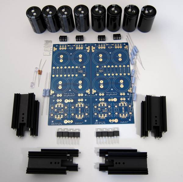
Anyway, I am a bit confused now after reading the first 60-70 pages of this thread, hoping to see the original board completed and hooked up. Do I need the thermistors and the same type of ground scheme as shown with the monolithic bridges situation?
I am all done until I build the chassis but now I need to know what additional parts I need, since none of these mentioned came with the F5 parts kit, and perhaps I am missing something from the PSU BOM?

When I bought this PCB, I ordered the BOM based on the parts shown in the beginning of this thread, including heat sinks, and it looked as if that's how this guide was going to go. It was even advised 'not' to separate the diode section if not needing to. Fast forward almost two years and now I see mention of not using the diode section and now there's talk of thermistors and other things that are not mentioned in this article's original start, nor in the BOM listed at the store.
This is the part of the BOM I bought, along with the optional resistors just to have them on hand in case I was understanding wrong, somehow for my purpose, which is the F5 V3.
Anyway, I am a bit confused now after reading the first 60-70 pages of this thread, hoping to see the original board completed and hooked up. Do I need the thermistors and the same type of ground scheme as shown with the monolithic bridges situation?
I am all done until I build the chassis but now I need to know what additional parts I need, since none of these mentioned came with the F5 parts kit, and perhaps I am missing something from the PSU BOM?
Last edited:
There are a few ways you can do it.
Most common is:
Two CL-60s acting as soft-start for common US wiring with dual primary/dual secondary transformer.
X1/Y1 rated cap.
One CL-60 for ground lift.
If you can't find pics etc. re-post.
You'll also potentially need a terminal block and your choice of terminations for mains / primary / secondaries.
This blog has an excellent walk-through (IMO) for how to set up and test your PSU. A monolithic bridge and CL-60 are used for the ground lift, which you could do if you like. They also have links to recommended parts if needed.
DIY Aleph J: A Build Guide
Mrboat, are you sure you need the blade-connectors at the output-side?
I decided to split my boards into a rectifier and CRC-board, so that the gap (1cm) allows better airflow to the inner heatsinks. (They haven’t been under load yet, but I guess they will get warm) here you can almost see it: https://www.diyaudio.com/forums/att...guide-building-pass-f4-amplifier-img_0468-jpg
I decided to split my boards into a rectifier and CRC-board, so that the gap (1cm) allows better airflow to the inner heatsinks. (They haven’t been under load yet, but I guess they will get warm) here you can almost see it: https://www.diyaudio.com/forums/att...guide-building-pass-f4-amplifier-img_0468-jpg
Last edited:
Mrboat, are you sure you need the blade-connectors at the output-side?
I decided to split my boards into a rectifier and CRC-board, so that the gap (1cm) allows better airflow to the inner heatsinks. (They haven’t been under load yet, but I guess they will get warm) here you can almost see it:
Not sure. Just added them per the build guide. I am building the chassis from scratch other than the heat sinks so I can make ample room for airflow, etc.
Thank you for showing a picture of your PSU as built with the original parts. Do you have your transformer wires running under the rectifier board?
Last edited:
- Home
- Amplifiers
- Power Supplies
- diyAudio Power Supply Circuit Board v3 illustrated build guide