The 45V+ version is no different in its output impedance than the original version.
The Kmultiplier's output impedance is comparable to that of large electrolytics. This basically means that if you put a 1000-2200uF lytic at the output, supply impedance will be halved. Another and it will be cut in third. So, wherever you want to end up, let this be your guide. Any lytic smaller than 470u probably won't have much of an effect unless it is closer to the circuit than the KM. A large film cap however will have low enough ESR to be an improvement in the ultrasonic range.
The Kmultiplier's output impedance is comparable to that of large electrolytics. This basically means that if you put a 1000-2200uF lytic at the output, supply impedance will be halved. Another and it will be cut in third. So, wherever you want to end up, let this be your guide. Any lytic smaller than 470u probably won't have much of an effect unless it is closer to the circuit than the KM. A large film cap however will have low enough ESR to be an improvement in the ultrasonic range.
I was considering this versus the Salas shunt for no other reason than cost and total junctions, but with the caps, the cost is higher. I am still curious if I will like it more, as the there are less transistors involved in the signal. Simple minded, i know, but just a theory.
60mm is longer than my thumb.
That puts 200mm in as a long dimension.
0.5nH to 1nH per millimetre of trace/wire adds up very quickly to raised HF impedance.
That is a new formulation of a Rule of Thumb
")
Kean,
Could you walk through the forumula for figuring the Zo of the K multiplier if it will be supplying a B+of 340mV@20mA. I have tried using the explanation on the site, but I am misunderstanding something, it seems.
For instance,
"Q1 is biased into it's most linear range by R1. So Ic(Q1) is roughly .68/47=~15mA. This is a bit low to accommodate for a nominal max of 5mA Ib(Q2)."
Is there conflict in this statement? Its 15mA, but a bit low for nominal 5mA for q2 base?
Last edited:
Rule of thumb was refering to width I believe about 25mm or 1inch approx. Still it adds up fast at higher freq.s .That is a new formulation of a Rule of Thumb
Been using Kmult behind Salas BiBs in my headphone amp with great results for a long time now. Sound is more uniform without harshness but keeping all the detail and "byte".
Tried to use the same behind FdW shunts on the paradise and got bad sounding high frequencies. seemed like distortion. Scoped it and found that I had ultra high freq modulations.... oscilations maybe.
Now I am experimenting it behind Salas folded and it works very well.... ripple comes down from 360mv to 80mv just before entering the shunts and I hear no distortions at all. Can not give a good subjective listening impression because I only have one channel running with the kmult.
Will now build another one and report the results latter.
KMult. CFP sims
I have run some sims on your KM and have found great currents on 100uF cap.
When powering a 100w amp, currents are up to 5A. Seems to me a huge current for a small capacitor !
If this cap were a bit small, we could substitute by a Film cap type and will be no electrolytic cap in the signal path.
Regards.
I can't say either way. But if you build the KM first to find out, you'll have them available when you use the shunts. In any case I'm curious what your result would be.
I have run some sims on your KM and have found great currents on 100uF cap.
When powering a 100w amp, currents are up to 5A. Seems to me a huge current for a small capacitor !
If this cap were a bit small, we could substitute by a Film cap type and will be no electrolytic cap in the signal path.
Regards.
Ib(Q2) is added to I(R1) and this becomes the collector current of Q1. We want to keep collector current under 20mA to keep Q1 in its linear range, so R1 has been chosen to accommodate Ib(Q2).
The output impedance of the Kmultiplier is the Rm (emitter resistance) of Q1 divided by the current gain of Q2/R1. The current gain of Q2/R1 is R1 divided by the Rm of Q2. Rm =~ 27mV/Ie, so we must know the bias current of each transistor first. The total load is 20mA, and the Q1 bias will be ~680mV/120R=5.7mA. So Ic(Q1)=5.7mA, Ic(Q2)=20mA-Ic(Q1)=14.3mA. The current gain of Q2/R1 will be 120R/(27mV/14.3mA)=~64. The output impedance will be the Rm of Q1 divided by this. 27mV/5.7mA=4.74R, 4.74R/64=74mR.
Luis, do you refer to the Kmultiplier in the link in my signature? If so, then I've made sure there are no such problems. I'd have to see your simulation to know exactly what was wrong.
.../...
Luis, do you refer to the Kmultiplier in the link in my signature? If so, then I've made sure there are no such problems. I'd have to see your simulation to know exactly what was wrong.
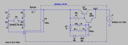
Signal Path is confined to that way in my sims.
Attachments
Well, after some homework I redesigned the kmult layout and build two positives to be able to listen to the arrangement inside one of my riaa builds.
Now the readings are much better, I have 44.5Vin with 300mV ripple and get 42.7Vout without measurable ripple. My scope presents a straight line with a variation of 800uV but no frequency so I do not know if it is ripple.
Anyway, inside the riaa case, before the shunts they are.
Will listen for a while to be able to present my subjective impressions but initially I noticed more presence in the bass....
Any 1N400x will do, that is a schematic error. I've fixed the schematic.
Luis, you are correct. However the Kmultiplier ignores AC at its input so any signals at its input are very well filtered.
I've just seen that your KM is not for power amps, and then there is no problem with small currents.
Regards.
Been using Kmult behind Salas BiBs in my headphone amp with great results for a long time now. Sound is more uniform without harshness but keeping all the detail and "byte".
......
Now I am experimenting it behind Salas folded and it works very well.... ripple comes down from 360mv to 80mv just before entering the shunts and I hear no distortions at all.
Do you mean you use KM between Salas Shunt and the headphone circuit board / load?
Wouldn't it better to have the KM at the front then Salas Shunt then the headphone?
Do you mean you use KM between Salas Shunt and the headphone circuit board / load?
Wouldn't it better to have the KM at the front then Salas Shunt then the headphone?
I do not believe it would produce any good results that way, Salas shunts output uniform voltage with really low noise and as they are shunts they can produce (and absorb) current surges... The Kmult can not do that.
IMO the Kmult acts as a very high value cap with low ESR but can not absorb current as the cap does.
I noticed an increase in bass detail and an "easier" presentation of the soundstage in the case of the headphone amp.
In the case of the folded simplistic, bass gains are also noticed but I somehow noticed an overall "muffle" effect.... I lost the mid freq immediacy and corresponding "attack"... soundstage lost some of it's magical width.
I must admit that I have been working in this folded build for a long time now and I know it responds even to Cap modifications in the raw psu.... I reached a "bliss point" where everything is in equilibrium and the kmult unsettles this eq.
I believe it could be successfully implemented but it would take a long time to "tune" with this new circuit on.
Anyway, I do not notice any reduction in noise (salas shunts are noiseless per se) so it is only an experiment for the sake of diy.
PS: I am also learning how to use my new scope so I need some guinea pigs...
RCruz,
I appreciate that you are getting better sound. but sorry I am still in the dark.
So when you get better sound, is it "AC -> Rectification -> Cap smoothing -> Salas Shunt -> KM -> load", or "AC -> Rectification -> Cap smoothing -> KM -> Salas Shunt -> load"?
Is it the first one or the second one above?
Thanks,
Bill
- Home
- Amplifiers
- Power Supplies
- Keantoken's CFP cap multiplier