Hi Mr. Salas,
I'm in the design phase of a new 6SN7 line preamplifier, and I came across your shunt regulator.
The preamplifier wiIl be based on a MU-Followe design, each channel drawing 4ma for a total of 8mA. The power supply transformer has 0-270V @30mA output, requested B+ is 310V. With a solid state rectifier I manged to get ~370V raw B, which I trimmed down to 330-340V. I have couple of questions:
1. I have a generic red led, do I need to look for some specific type?
2. Is the raw B too high? The voltage changes quite a lot (~10V) over the day. I'm planning to use the chassis side panel as a heatsink for Q3 and going to install on Q1 the one recommended in your guide.
3. Given that the preamplifier current consumption is 8mA, what is the current drawn from the SSHV2 by itself ? Will the transformer be ok ?
Thank you very much.
1. Generic is fine
2. Not too high yet
3. 20mA spare CCS current setting over load demand is recommended for SSHV2. The less spare, the higher its output impedance. The transformer does not look good in this application if only 30mA rated.
*Note that a transformer's secondary current AC rating reduces by 0.62 for DC current in a full bridge capacitor input situation.
Hi Salas, I came across this thread last night when searching for info on a HV regulator. It's difficult to run thru all 600+ pages of info so I just drop the question here. I plan to build a "low" HV reg with 125V output. I looked at your design and found that you use 2SK170 as CCS in your version. But the 2SK170 Drain Source voltage plus the voltage drop across the trim pot is limited to 0.6V, the Vbe of the MJE350, I wonder if this is too low for the CCS to work properly. I think a couple of volts might be needed.
Hi
I assume you refer to SSHV1 but the ref design base is the same. It has also been explained analytically in the past of course.
In brief, Njfet Vgs is minus so it extends the Vds voltage available because PNP Vbe is minus too so they sum to a larger number. That and being used low in the Id vs Vds curves here, K170 enters the saturation region early enough. Just fitting. There's also a way to lift the PNP transistor at the emitter with diodes or a small voltage Zener to increase K170 CCS PSRR but it also has a negative impact on output impedance spec. I knew that and I opted for lower Zout on the pros and cons balance.
Let's not forget this regs family Is about simplistic FET designs not targeting great Vref PSRR spec or rock solid drift performance but a low parts count and a different sound than high feedback series type regulators. In HV audio world with tubes, rail precision performance is fortunately more slack a demand.
1. Generic is fine
2. Not too high yet
3. 20mA spare CCS current setting over load demand is recommended for SSHV2. The less spare, the higher its output impedance. The transformer does not look good in this application if only 30mA rated.
*Note that a transformer's secondary current AC rating reduces by 0.62 for DC current in a full bridge capacitor input situation.
Ok looks like I need a new transformer!
So back to the RAW B design.
1. I will ask for an 100mA transformer I think should be fine, what you think ?
2. The design will be again quite simple with a diode bridge and a CRC filter. In order to calculate the R should I consider 8mA drawn from the preamplifier plus 20mA drawn from the SSHV2 ?
3. Do you recommend a more sophisticated design ?
Thank you very much for your help.
Francesco
Thanks, I did expect you explained it already and I am lazy enough not to read thru all 6000 posts. Looking into the 2SK170 spec with 1mA drain current, the FET close to saturation with Vgs at -0.3V. This will drive Vds to about 1V. I understand your rationale and this certainly is helpful to me. I do not have 2SK170 but a few 2SK30A. Following your idea I will drive them at 0.5mA, giving a Vgs of about -1V and a Vds of 1.6V. This goes well into the saturation region. Thanks
@franco
1. It should suffice
2. Consider the total current drawn. In other words set for load + spare 8+20=28mA. Thus 30mA setting is good
3. CRC is good enough, unless you have a spare choke for CLC which is even better if not used near its saturation spec
Thanks for you exhaustive answer.

I have no clue as to why, above my pay grade. I discovered it while testing with a bench power supply, i was aiming for a 150v reg output with the CCS Set for 25ma. Anything below ~190v B+ and the output voltage started to drop and wouldnt let me adjust it any higher. ~43v was the point where it all started to work properly.
Final design has 225v B+ and 165v reg output so there is 60v across the regulator to keep it happy.
Final design has 225v B+ and 165v reg output so there is 60v across the regulator to keep it happy.
Last edited:
Hello Salas,
I am starting to build the SSHV2, the C1 is confirmed by Wima MKP100.33UF, the C2 I am confused because the volume of Wima DC-link 800V 10uf I received is smaller than the volume of Wima MKP4400V 6.8uf I believe in bulk, will SSHV2 performance degrade if C2 is changed to 6.8 UF?
Thank you!
View attachment 943094
View attachment 943095
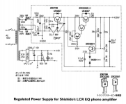
Salas SSHV2 for phono stage
Hello all!
What do you think if replacing the stock regulator circuit of Shishido LCR phono stage with Salas SSHV2.
I am going to use transformer with 225vac on secondary, is that adequate? How much reservoir should I use in such a power supply?
Thanks in advance!
Hello all!
What do you think if replacing the stock regulator circuit of Shishido LCR phono stage with Salas SSHV2.
I am going to use transformer with 225vac on secondary, is that adequate? How much reservoir should I use in such a power supply?
Thanks in advance!
Attachments
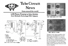
SSHV2 looks proper for this use. Don't know if you will ultimately prefer it over the stock regulator series design, but with a shunt reg the phono should sound somewhat different.
225VAC Tx with full bridge rectifier should be adequate. 100uF 100R 100uF CRC reservoir is enough. Also 0.1uF decoupling capacitor across SSHV2's DC input if there is wiring distance to the reservoir.
225VAC Tx with full bridge rectifier should be adequate. 100uF 100R 100uF CRC reservoir is enough. Also 0.1uF decoupling capacitor across SSHV2's DC input if there is wiring distance to the reservoir.
SSHV2 looks proper for this use. Don't know if you will ultimately prefer it over the stock regulator series design, but with a shunt reg the phono should sound somewhat different.
225VAC Tx with full bridge rectifier should be adequate. 100uF 100R 100uF CRC reservoir is enough. Also 0.1uF decoupling capacitor across SSHV2's DC input if there is wiring distance to the reservoir.
Can I use Menno Vanderveen MEC electronic choke instead of the 100R resistor?
- Home
- Amplifiers
- Power Supplies
- Simplistic MosFET HV Shunt Regs