I searched the web for information on the mechanisms of distortion in ribbon speakers, but I found only hypotheses, reasoned and even shareable suppositions, but no ad hoc measures. Maybe those who make these speakers know all about the subject, but if so, they keep it to themselves. So being a DIY enthusiast of ribbons, I decided to do some research, within the limits of my cognitive and economic possibilities.
One of the assumptions that everyone (myself included) has made is that a primary mechanism of distortion arises from the non-uniformity of the magnetic field
The distance between the pole pieces, having to contain the width of the strip, is always relatively large with respect to the height of the expansions themselves, therefore it is normal for the ribbon, during large movements, to operate within very different magnetic flows.
So as a first step I wanted to verify and possibly quantify this hypothesis.
As a first approach to see how much magnetic field uniformity affects THD I used the ribbons in closed box which I have already extensively described in another thread, my ribbons full range in CB - diyAu...ngine Long_base_field Long_base_0 Long_base_8
Attachments
Last edited:
The ribbons (just over 2 Ohm) are each driven directly by their own dedicated amp. The 2 amps are identical and without response corrections
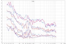
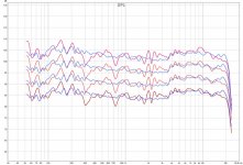
I made THD measurements using the REW program and the calibrated UMIK microphone placed 15 cm away from the ribbons and on the approximately central axis. The measurements are related to 4 input signal levels, in 6 dB steps. The curves in red refer to the left box with the shaped pole pieces, while the blue refers to the right box with the flat, traditional pole pieces. I remind readers that these are ribbons with side suspension.
Box_overlay SPL
the plots of the left box are more bumpy because the case is leaning against a side wall as well as the back wall
Box_overlay THD
Here I am surprised, because the differences between red and blue do not seem significant to me, in the face of very different uniformity of magnetic fields. So I conclude that a bad uniformity of the magnetic field does not affect the THD, even at low frequencies where the excursion of the ribbons is large. I find it strange but these are the results. The phenomenon that I notice and do not like instead is that while the SPLs increase by 6 dB per step, the THDs increase more, 10-13 dB per step, in particular at low and medium frequencies, up to about 3.5 KHz (I don't take into consider the very low THD parts, close to ambient noise). I make similar measurements on a pioneer moving coil woofer and I find that a 6 dB increase in SPL corresponds to an increase in THD of about 8-9 dB
Attachments
On the same speakers I measured the Intermodulation Distortion (IMD) at 2 tones, 50 Hz and 8000 Hz, using 3 levels (dB with arbitrary reference) and the same object arrangement used to measure THD. The ratio between the amplitudes at 50 Hz and 8000 was 4: 1. I adjusted the amplitude of the electrical signal sent to the left speaker in order to have the same RMS audio input relative to the right speaker. REW gave the following results (d2L = 2nd harmonic distortion of the 50 Hz frequency, d2H = 2nd harmonic distortion of the 8000 Hz frequency)
box left right left right left right
Electr. input -26 dB -18 dB -12 dB
audio RMS 85,3 dB 85,2 dB 93,6 dB 93,5 dB 100,0 dB 99,9 dB
IMD 3,19 % 6,72 % 7,84 % 17,4 % 17,1 % 33,8 %
d2L 2,53% 4,86% 6,37% 11,9% 13,6% 24,5%
d2H 1,93% 4,62% 4,56% 12,7% 10,2% 24,5%
d3L 0,085% 0,25% 0,31% 0,65% 1,20% 3,26%
d3H 0,023% 0,23% 0,067% 0,58% 0,40% 3,68%
Here you can see the difference between uniform and non-uniform magnetic fields: With the same RMS audio input, the IMD of the driver with a more uniform magnetic field is substantially lower, about half that of the other driver.
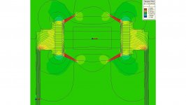
At this point I have to check how much the side suspensions have to do with it: I make other measurements with another test engine, only 25 cm long, where first I put shaped pole pieces and then I repeat the measurements after changing the pole pieces with other flat, traditional ones. .
Motor A with shaped pole pieces:
5x25d41real
5x25d41real_field
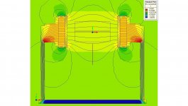
The field is overcompensated, but I already had those polar expansions and then I didn't have the possibility to do them ad hoc. However, it is much more uniform than that of motor B, with flat pole pieces:
5x25d41base
5x25d41base_field
I used a ribbon similar to that of the boxes above, but suspended only at the ends, as is classic: Alu 12 um, 4 strips respectively 6.6,6,6 mm wide held together by 12 g / m^2 paper and connected in series, with an overall resistance of 0.54 ohm, zinc plated ends to avoid contact problems. The amp is one that I always use for testing, capable of delivering up to 25 A peak to the load, the coupling is direct with no transformer and no R in series.
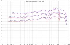
The result is similar to that with the side suspensions: these are the SPL graphs with the microphone at 6 cm (red is relative to motor A, compensated, blue to motor B. The voltage across the ribbon are respectively 0.57, 1.13 and 2.26 Vpp).
Short motor, no l_s spl
The dip at about 3 KHz is due to reflections from the desk and other nearby objects, while the dip at just over 10 KHz is due to the shaping of the pole pieces of the compensated motor
Short motor,no l_s thd
Only below 200 Hz and with increasing SPL there is a lower THD with the motor with a more uniform field. Between 400 Hz and 1.5KHz there is the anomalous increase in THD seen before,, while elsewhere it is almost normal in both cases.
box left right left right left right
Electr. input -26 dB -18 dB -12 dB
audio RMS 85,3 dB 85,2 dB 93,6 dB 93,5 dB 100,0 dB 99,9 dB
IMD 3,19 % 6,72 % 7,84 % 17,4 % 17,1 % 33,8 %
d2L 2,53% 4,86% 6,37% 11,9% 13,6% 24,5%
d2H 1,93% 4,62% 4,56% 12,7% 10,2% 24,5%
d3L 0,085% 0,25% 0,31% 0,65% 1,20% 3,26%
d3H 0,023% 0,23% 0,067% 0,58% 0,40% 3,68%
Here you can see the difference between uniform and non-uniform magnetic fields: With the same RMS audio input, the IMD of the driver with a more uniform magnetic field is substantially lower, about half that of the other driver.
At this point I have to check how much the side suspensions have to do with it: I make other measurements with another test engine, only 25 cm long, where first I put shaped pole pieces and then I repeat the measurements after changing the pole pieces with other flat, traditional ones. .
Motor A with shaped pole pieces:
5x25d41real
5x25d41real_field
The field is overcompensated, but I already had those polar expansions and then I didn't have the possibility to do them ad hoc. However, it is much more uniform than that of motor B, with flat pole pieces:
5x25d41base
5x25d41base_field
I used a ribbon similar to that of the boxes above, but suspended only at the ends, as is classic: Alu 12 um, 4 strips respectively 6.6,6,6 mm wide held together by 12 g / m^2 paper and connected in series, with an overall resistance of 0.54 ohm, zinc plated ends to avoid contact problems. The amp is one that I always use for testing, capable of delivering up to 25 A peak to the load, the coupling is direct with no transformer and no R in series.
The result is similar to that with the side suspensions: these are the SPL graphs with the microphone at 6 cm (red is relative to motor A, compensated, blue to motor B. The voltage across the ribbon are respectively 0.57, 1.13 and 2.26 Vpp).
Short motor, no l_s spl
The dip at about 3 KHz is due to reflections from the desk and other nearby objects, while the dip at just over 10 KHz is due to the shaping of the pole pieces of the compensated motor
Short motor,no l_s thd
Only below 200 Hz and with increasing SPL there is a lower THD with the motor with a more uniform field. Between 400 Hz and 1.5KHz there is the anomalous increase in THD seen before,, while elsewhere it is almost normal in both cases.
Attachments
Last edited:
I also measured the IMD with F1 = 35Hz and F2 = 9000 Hz, ratio 1: 1, Umik mic at 6 cm, audio input about 86 dB in both cases. With the classic engine it was IMDtot = 12.7%, while with the compensated engine it was 5.67%.
At this point I can hazard a few conclusions:
1) For frequencies from a few hundred Hz up (I would say from 300-500 Hz), the non-uniformity of the magnetic field is not at all responsible for a high THD. Perhaps eliminating the real primary cause of distortion would reveal a difference due to the non-uniform field, but for now the result is this. The explanation is trivial: The ribbon's excursions are minimal even at high levels.
2) A tweeter or even a ribbon mid have no problems deriving from motors with uneven magnetic fields, while a full-range certainly would have
3) The primary cause (s) of distortion still remain hypothetical
Last edited:
Hello to Jedi
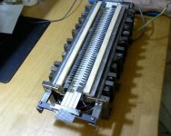
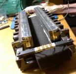
I have not yet given details on the shape of the polar expansions, so I am attaching a photo. I actually obtained the tapering of the thickness with a constant thickness shaping of the longitudinal profile. The simulations of the field in the 2 cases give almost identical results
If you mean linear distortion (deviation from the flat trend of the frequency response) surely yes, and it is visible in the curves I posted, but it is my belief that a partial obstacle in front of the ribbon does not affect the total harmonic distortion (THD), otherwise AMT, ESL and push-pull isodynamic drivers would be crap
Attachments

As far as I remember it the RAVEN ribbons had very low distortions!
They were constructed in France or a french guy ... maybe a websearch reveals more info .
The Ravens have iron poles so induction current could case electromagnetic damping of the motion .
But first please measure if the transformer contributes significantly to the total distortion ... and any static magnetic field should be avoid due to partial saturation .
The original designer Alain Bernard is dead now ... info about Raven ribbons use Google Images/Pictures ... I found this one but not sure if it is still in production :
Line Source – Raven Design Studio
With iron-pole ribbon designs , some say dynamics are suppressed , sounds true to me because of the induced currents in the iron pole (remember virtual current is very high on the secondary XFormer winding) which reflects back on the ribbon that has very low driving force (BL - Factor) ... and all modern ribbon designs have neodym magnets on the sides!
Btw - seems due to economic wars the prices of neodymium will probably eXplode in the next months ...
Ribbon design is a tough job!
ps: .. some info about misc ribbon designs ... Speakers - Ribbons
Last edited:
Hello Marveloudio
I have no direct knowledge of the Raven's ribbons. What I can say is that they are limited in band from 800 Hz and up, and I don't like to put crossovers, which become the weak link in the chain. However the object of this forum is to experimentally investigate the mechanisms of ribbons distortion, and I don't think Raven gives any information about it, apart from the usual bla bla: "our ribbons are wonderful, wonderful, the best in the world" etc. . The influence of induced currents, or that is the same, the modulation of the magnetic field by the current in the ribbon, will be the topic of the next posts.
But first please measure if the transformer contributes significantly to the total distortion ... and any static magnetic field should be avoid due to partial saturation. [/ QUOTE]
In post # 3 I have already specified that I don't use transformers
At this point I wanted to verify if the modulation of the magnetic field by the current had something to do with it. Not that I believe it possible, because according to the simulations I made the variations of the field due to the current in the ribbon are irrelevant, but since it is a hypothesis advanced by some I decided to verify it.
So I made a comparison between the distortion of the same ribbon mounted first on a motor with a magnetic field of about 0.1T obtained with 5 mm thick magnets and then on another with double the magnets (10 mm total thickness) and an adequate increase of the section of the iron closing the magnetic field, therefore with a magnetic field about double, of 0.2T. In this situation 2 things happen:
1) the same current in the 2 cases causes a percentage variation of the magnetic field smaller in the motor with a higher magnetic field
2) for the same SPL produced, the current in the ribbon on the motor with a higher magnetic field is much smaller
Therefore, any effect of modulation of the field by the current should be substantially less, for the same SPL, in the motor with a higher magnetic field.
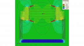
To be sure of the results I checked the magnetic field simulations with measurements. In the following I will call motor A10 the one with double magnets and compensated with shaped pole pieces, and motor B10 the one with double magnets and flat pole pieces, while A5 and B5 resp. the motors previously called A and B.
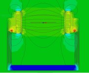
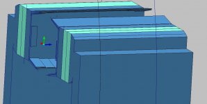
For the sake of brevity, I define the axes as shown in the figure: red = X, green = Y, blue = Z
Origine
Motor A10
(10x25d35_3d1)
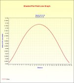
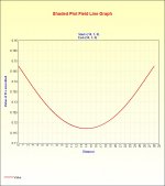
10x25d35_3d1_field (magnetic field in the plane YZ, and X=0)
Motor B10 (10x25d35_base)
10x25d35base3d_field (magnetic field in the plane YZ, and X=0)
So I made a comparison between the distortion of the same ribbon mounted first on a motor with a magnetic field of about 0.1T obtained with 5 mm thick magnets and then on another with double the magnets (10 mm total thickness) and an adequate increase of the section of the iron closing the magnetic field, therefore with a magnetic field about double, of 0.2T. In this situation 2 things happen:
1) the same current in the 2 cases causes a percentage variation of the magnetic field smaller in the motor with a higher magnetic field
2) for the same SPL produced, the current in the ribbon on the motor with a higher magnetic field is much smaller
Therefore, any effect of modulation of the field by the current should be substantially less, for the same SPL, in the motor with a higher magnetic field.
To be sure of the results I checked the magnetic field simulations with measurements. In the following I will call motor A10 the one with double magnets and compensated with shaped pole pieces, and motor B10 the one with double magnets and flat pole pieces, while A5 and B5 resp. the motors previously called A and B.
For the sake of brevity, I define the axes as shown in the figure: red = X, green = Y, blue = Z
Origine
Motor A10
(10x25d35_3d1)
10x25d35_3d1_field (magnetic field in the plane YZ, and X=0)
Motor B10 (10x25d35_base)
10x25d35base3d_field (magnetic field in the plane YZ, and X=0)
Attachments

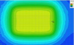
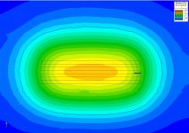
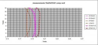
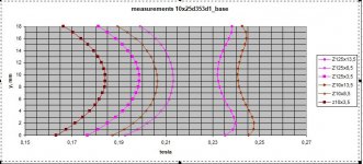
Note that the range of colors in both plots is from 0T (blue) to 0.25T (red) in 21 colors
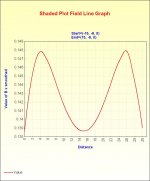
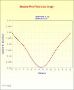
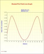
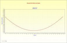
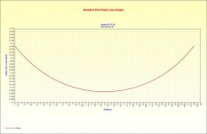
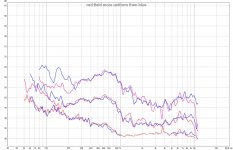
Since in the simulations I noticed that the tolerance on the dimensions of the pole pieces is quite small, for safety I measured the Bx component with a Hall probe, both for Z = 125mm, (center of the motor) and for Z = 10mm (near 1 end ) by moving the probe along Y (direction of movement of the ribbon) I measured Bx on 3 values of X: Resp. 13.5, 8.5 and 3.5mm, in order to cover the entire width of the ribbon (27mm)
. The purple color refers to the measurements at Z = 125mm, while the brown color is for the measurements at Z = 10mm. In the 2 graphs I have kept the same scales for ease of comparison
Motor B10
10x25d35base_meas
Motor A10
10x25d35 3d1_meas
Attachments
At this point the engines are characterized and I can move on to the measures. I have used several ribbons, but since the results are the same, for the sake of brevity I will report the measurements for only one. The width of the magnetic field is 35 mm, while that of the ribbons 27 mm to avoid turbulence problems in the gaps.
C21A su 5x e 10x_base_SPL
C21A su 5x e 10x_base_THD
C21A su 5x e 10x_comp_SPL
C21A su 5x e 10x_comp_THD
C21A su 5x e 10x_base_SPL
C21A su 5x e 10x_base_THD
C21A su 5x e 10x_comp_SPL
C21A su 5x e 10x_comp_THD
Attachments
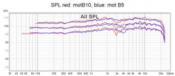
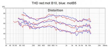
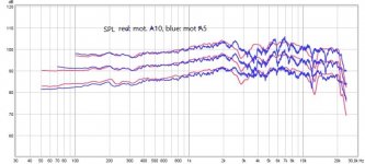
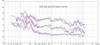
I don't see significant differences in THDs, with the same SPL, so I conclude that:
The modulation of the magnetic field by the current in the ribbon, if any, is negligible.
As for what some claim, that iron pole pieces reduce distortion with a mechanism similar to that of the copper ring on moving coil speakers, it definitely seems to me like a propaganda fable.
So I ask myself: If the primary cause (s) of the distortion of a ribbon is not the non-uniform magnetic field (excluding low frequencies) nor the modulation of the magnetic field, which is it? The only culprit remains the ribbon, you want the non-linear suspensions, you want the ribbon's selfmodes, so on and on. If any of you have ideas about it or criticism of what I have written, it is welcome, as I am going to start investigating the ribbon itself (I still don't know how)
You shall drive the ribbons with an transconductance amplifier NOT a voltage amplifier.
The current is the factor that gives the force to the ribbon, not the voltage.
Try to add 20 ohms resistor in series with the ribbon and redo the distortion measurements.
Or built a current feedback amplifier directly...
The current is the factor that gives the force to the ribbon, not the voltage.
Try to add 20 ohms resistor in series with the ribbon and redo the distortion measurements.
Or built a current feedback amplifier directly...
Hi esl 63
Thanks for the suggestion. I had already noticed, on occasion, that putting an R in series decreased the distortion, but only in some cases, while in others it increased it. Then I thought about some setup anomalies, but now I'll do some systematic comparative measurements. I am not totally convinced, as being the ribbon impedance similar to a pure resistance, a current driving should not make a difference compared to a voltage one. Furthermore, with current driving, the damping effect of the movement of the ribbon would be lacking and therefore perhaps the transient response will not be the same. But it's worth a try. Thanks
Thanks for the suggestion. I had already noticed, on occasion, that putting an R in series decreased the distortion, but only in some cases, while in others it increased it. Then I thought about some setup anomalies, but now I'll do some systematic comparative measurements. I am not totally convinced, as being the ribbon impedance similar to a pure resistance, a current driving should not make a difference compared to a voltage one. Furthermore, with current driving, the damping effect of the movement of the ribbon would be lacking and therefore perhaps the transient response will not be the same. But it's worth a try. Thanks
Although I haven’t investigated it myself, I know this is something that diyAudio member lowmass had posted about quite a few times. I was surprised to see he hadn't jump in, but looks like he hasn’t posted in some time. Reading between the lines of a few of his earlier posts seems to say that distortion is affected by size of the airgap and stiffness of the ribbon.…If the primary cause (s) of the distortion of a ribbon is not the non-uniform magnetic field (excluding low frequencies) nor the modulation of the magnetic field, which is it? The only culprit remains the ribbon, you want the non-linear suspensions, you want the ribbon's selfmodes, so on and on. If any of you have ideas about it or criticism of what I have written, it is welcome, as I am going to start investigating the ribbon itself (I still don't know how)
Here are links to a few relevant posts, most of which you were no doubt aware of.
Also attached are a couple ribbon patents that mention the effect of airgap width on distortion.
DIY ribbon dipole tweeter, reductio ad minimum
DIY ribbon dipole tweeter, reductio ad minimum
benefits and drawbacks of waveguides
my ribbons full range in CB
my ribbons full range in CB
Attachments
Please try playing a 1/3octave wide pink noise using your planars , ribbons , AMTs , whatever ...
all of them have some sort of quasi-chaotic behaviour due to small imperfections over the surface , or structured current density along conductor shape/size/layout ...
Pink Noise shows no masking effects like wide range noise so it's perfect for detection of disortions by ear .
Sinusodical exitation is usually no problem but pink noise is another story .
Please try it for yourself at low or normal/typical level , with filter of course to avoid over-excursion in the lower freq range.
You will need high quality WAV files for testing ... these should fit : High Definition Audio Test Files
It's a quick test not much effort ... good luck!
bye
- Home
- Loudspeakers
- Planars & Exotics
- On the Distortion of Ribbon Speakers