Going all in
To get the results above I had to make the iron part out of 5x40, 2x15 and 3x10 mm iron rods:
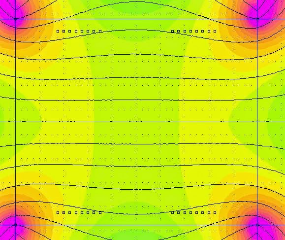
Resulting is this simulation overview:
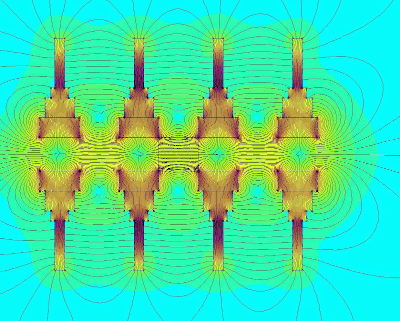
So the field is a little bit stronger and a wider linear area can be used.
To get the results above I had to make the iron part out of 5x40, 2x15 and 3x10 mm iron rods:
Resulting is this simulation overview:
So the field is a little bit stronger and a wider linear area can be used.
Last edited:
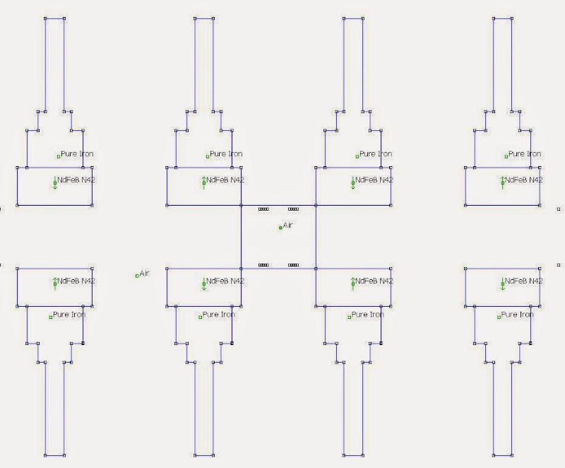
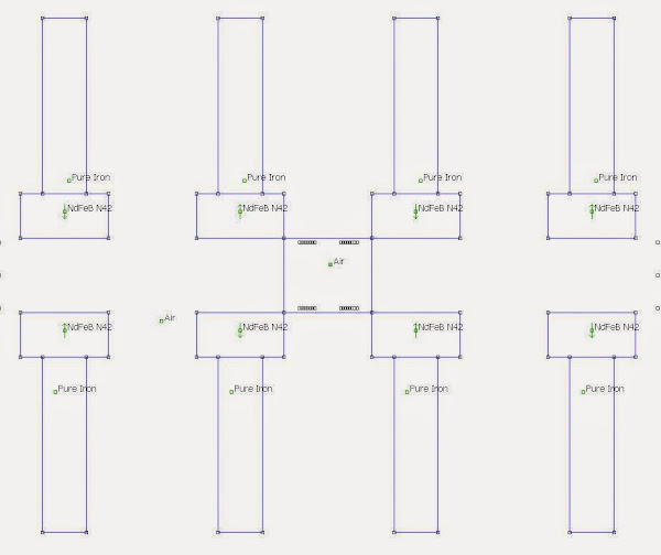
You can make the field a bit wider and linear using iron bars crossing like this:
 [/url][/IMG]
They are welded
 [/url][/IMG]
 [/url][/IMG]
Bernt
They are welded
Bernt
Yeah, but you need to cover the iron full length in order to get that field; it only exists where the bars are.
And, if you cover the iron full length, where does the air escape?
And, if you cover the iron full length, where does the air escape?
Behind iron bars
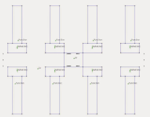
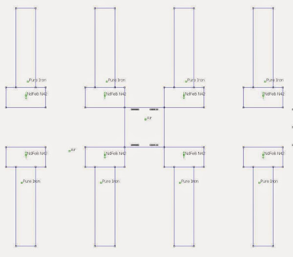
Started on the composite iron bars, but found them a little bit troublesome to make.
So I simplified them a little bit; only having two 5x40 mm for each magnet column.
Also thought a little bit on how to mount them into a frame and came to the conclusion that the distance between the front and back magnet assemblies could be alterable.
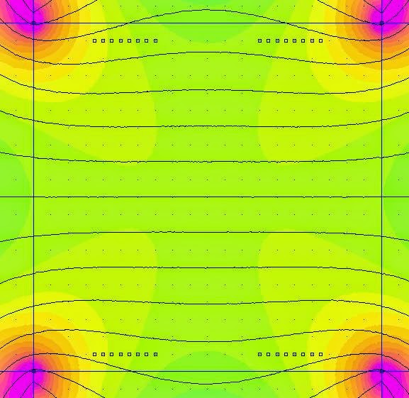
So here are the new magnet systems 15, 17 and 20 mm apart:
15 mm, the field is the middle is 0,36 T.
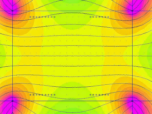
17 mm, the field is the middle is 0,35 T.
20 mm, the field is the middle is 0,32 T.
Started on the composite iron bars, but found them a little bit troublesome to make.
So I simplified them a little bit; only having two 5x40 mm for each magnet column.
Also thought a little bit on how to mount them into a frame and came to the conclusion that the distance between the front and back magnet assemblies could be alterable.
So here are the new magnet systems 15, 17 and 20 mm apart:
15 mm, the field is the middle is 0,36 T.
17 mm, the field is the middle is 0,35 T.
20 mm, the field is the middle is 0,32 T.
My idea was to use crossing bars 10x10mm 40mm spacing. 75-80% airflow.I can't Draw it in 2D.
Your new design is much easyer to make ,and if you does,t have a welding machine ,this is the way to do it.
These are wery strong magnets,so be very very careful handling the bars with magnets on.
And please share your idea to Mount the magnetsystems in the "frame",and the frames in front of each other.
Keep up the good Work.And be carefull.
Bernt
Yes, I understood that. It will still not be a continuous field strenght along the bars full length.My idea was to use crossing bars 10x10mm 40mm spacing. 75-80% airflow.
The crucial thing is to glue the magnets to the iron bars. I have used Loctite Power Epoxy Metal, but I think it cures too fast and does't make strong bound. The magnets come off very easy when I dismount a completed bar from the helper.Your new design is much easyer to make ,and if you does,t have a welding machine ,this is the way to do it
Going back to standard, slow curing epoxy...
As soon as I have something to share, I'll show it. It is always good with feedback.And please share your idea to Mount the magnetsystems in the "frame",and the frames in front of each other
Don't I now it 😱These are wery strong magnets,so be very very careful handling the bars with magnets on.
BTW, the Magnaprobe proved to be very useful when double checking the magnet's orientation.
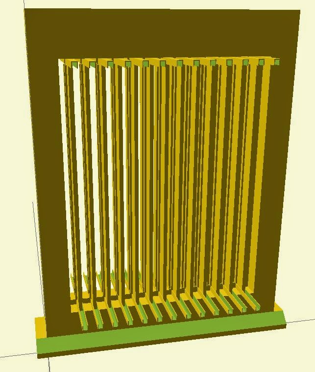
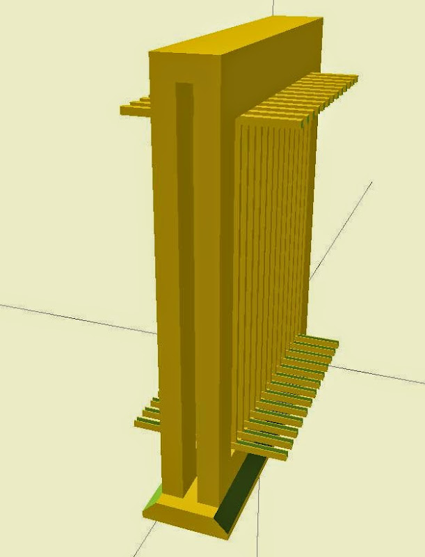
Here's my idea of a framework for the magnet system.
(Sorry about the proportions, but the first three pictures is correct.)
Front frame fixed on a base and with a top:
With the back frame that will be able to slide on base and top:

Magnet system:
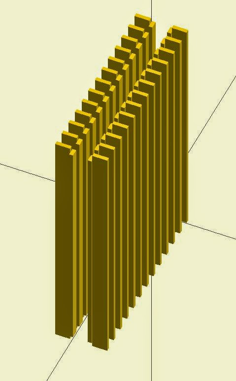
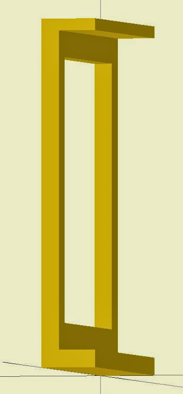
Barholders in the frames:
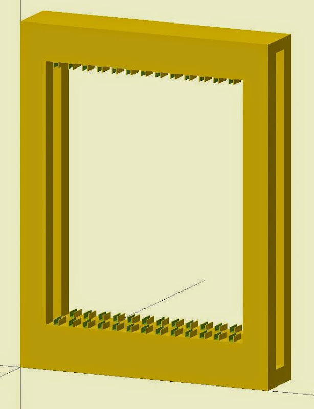
Complete frame:
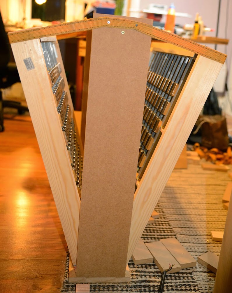
So the membrane in its own frame goes in between the frames.
As the front and back magnet system will repel, the front and back frames will be connected via some "nuts and bolts". That way the distance between them can be adjustable.
Some other views, with top removed and so on:
(Sorry about the proportions, but the first three pictures is correct.)
Front frame fixed on a base and with a top:
With the back frame that will be able to slide on base and top:
Magnet system:
Barholders in the frames:
Complete frame:
So the membrane in its own frame goes in between the frames.
As the front and back magnet system will repel, the front and back frames will be connected via some "nuts and bolts". That way the distance between them can be adjustable.
Some other views, with top removed and so on:
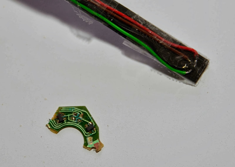
Made use of my Hall-element when I checked if I could use some 5-year old magnets from a scrapped ribbon speaker.
The element is not linear enough to do close up measurements but from a distance it is.
The measurements showed the same value, around 48 mV, when holding the element at 7 cm distance.
As they were almost the same, I didn't bother to make any more measurements.
The element is not linear enough to do close up measurements but from a distance it is.
The measurements showed the same value, around 48 mV, when holding the element at 7 cm distance.
As they were almost the same, I didn't bother to make any more measurements.
I am using Loctite Speedbond 326 now. It cures anaerobic and is a little bit faster.
It is still a slow job; I'm half way through the second batch of total 13:
Meanwhile I am trying to make a frame:
This is probably too weak though.
I did a first test of mounting the second bar, scary.
But had to abort the test. I must have some mounting aid here as well.
It is still a slow job; I'm half way through the second batch of total 13:
Meanwhile I am trying to make a frame:
This is probably too weak though.
I did a first test of mounting the second bar, scary.
But had to abort the test. I must have some mounting aid here as well.
Last edited:
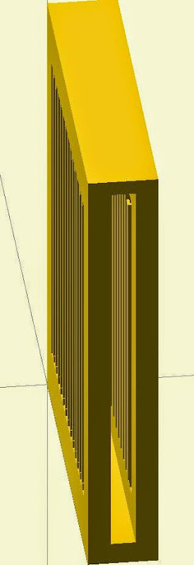
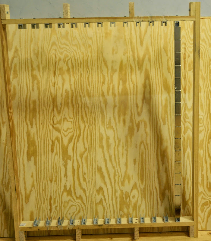
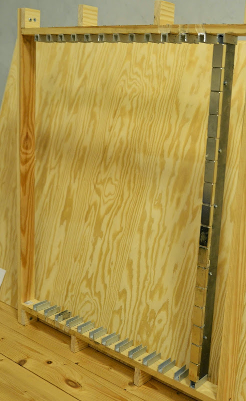
New frame
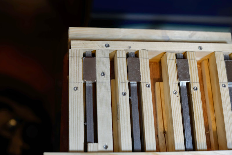
Except from sturdier frame, the bar holders can be made longer so the magnet bars can be slided into place:
After all testing is done, the bar holders can be cut back to to the frame.
Except from sturdier frame, the bar holders can be made longer so the magnet bars can be slided into place:
After all testing is done, the bar holders can be cut back to to the frame.
Finally
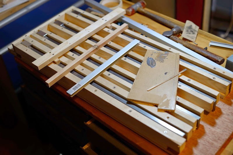
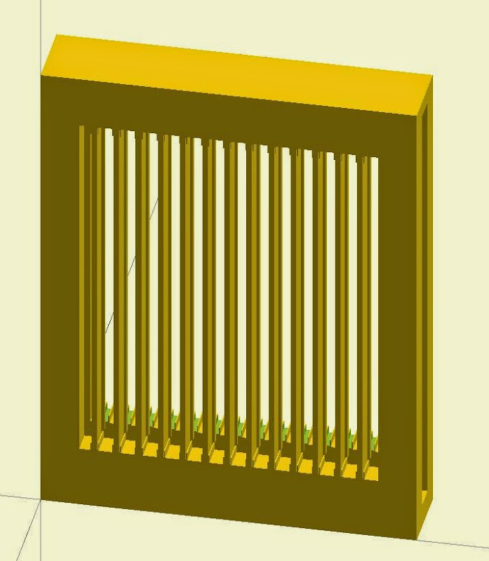
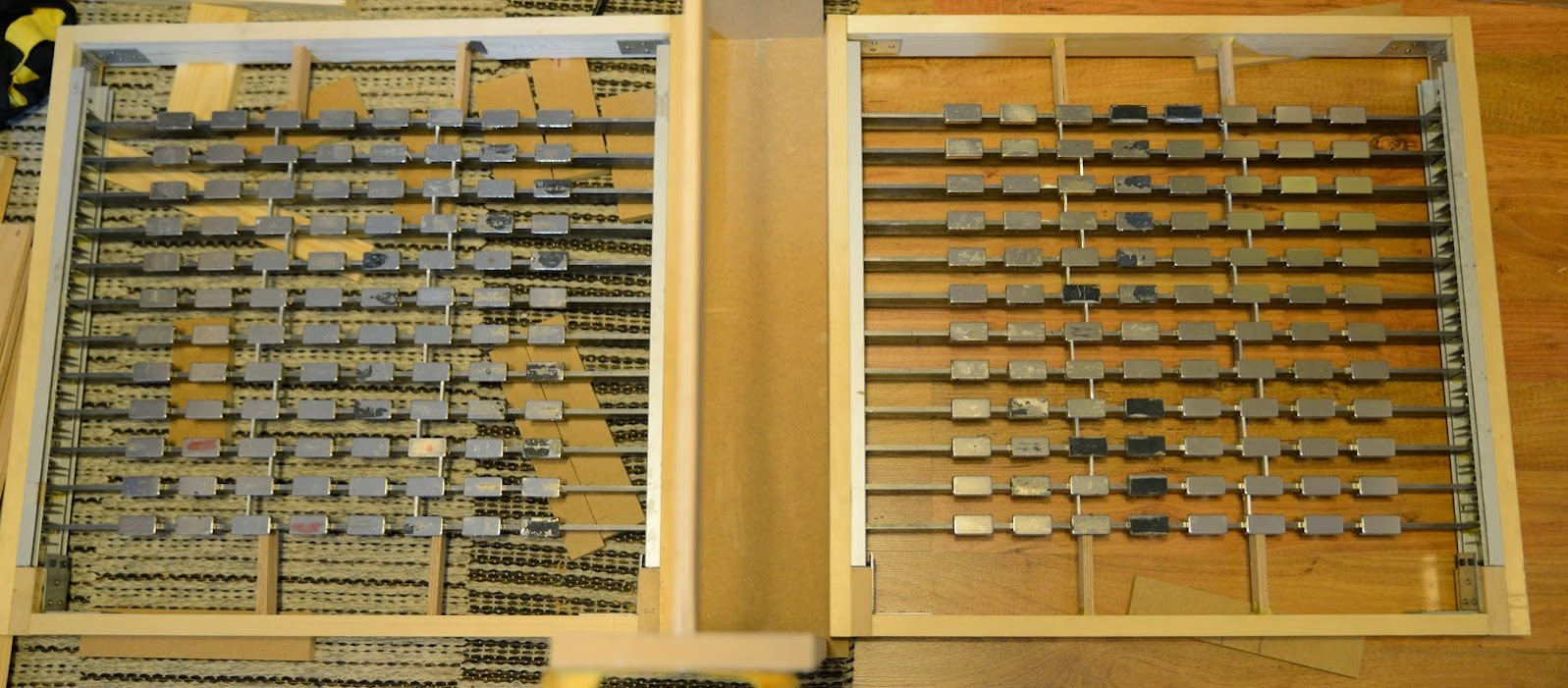
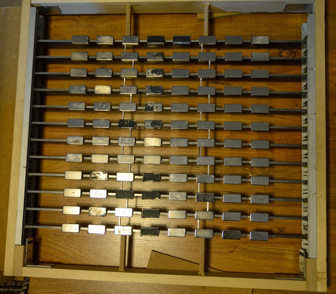
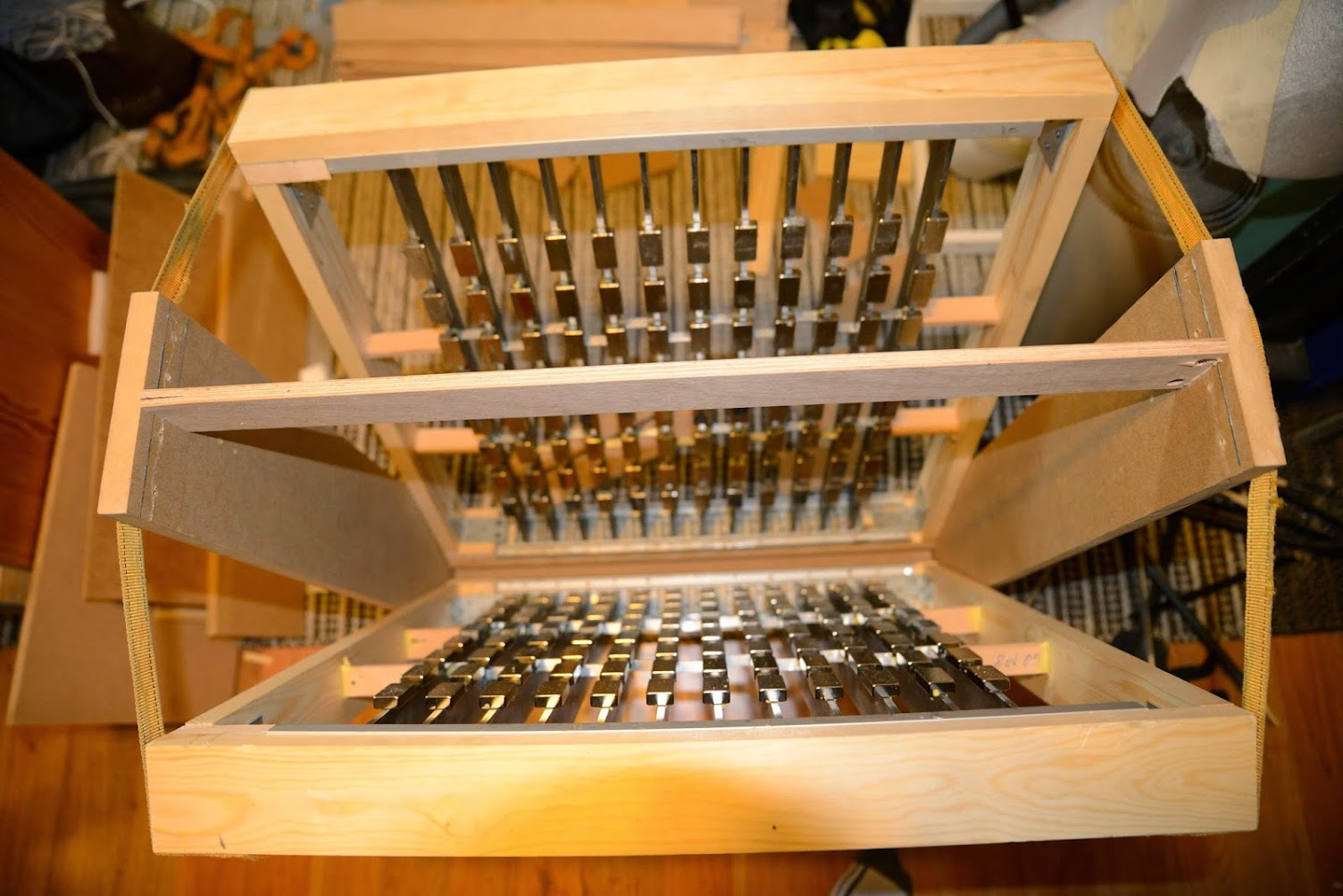
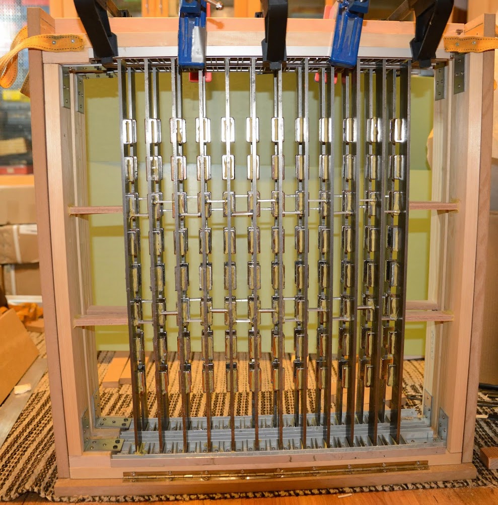
After several months of failures I finally have arrived at a sound construction:
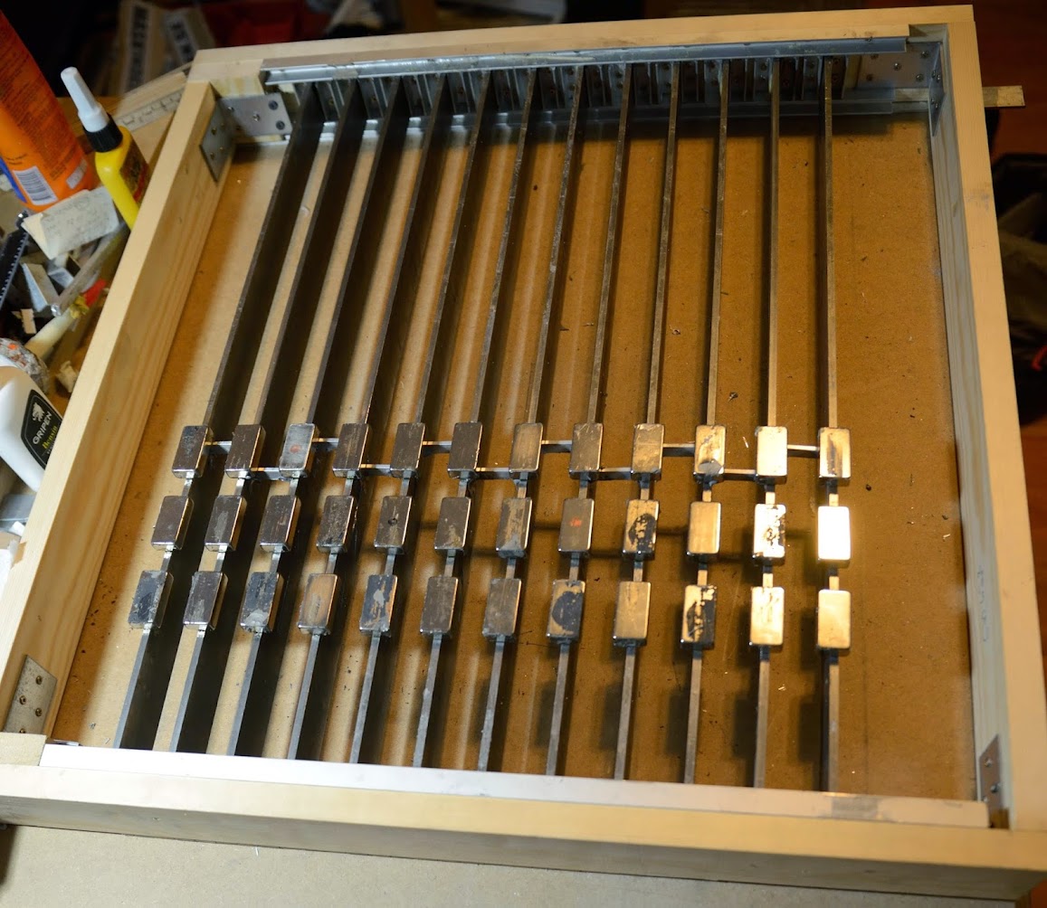
Magnets are North/South oriented both vertically and horisontally.
After several months of failures I finally have arrived at a sound construction:
Magnets are North/South oriented both vertically and horisontally.
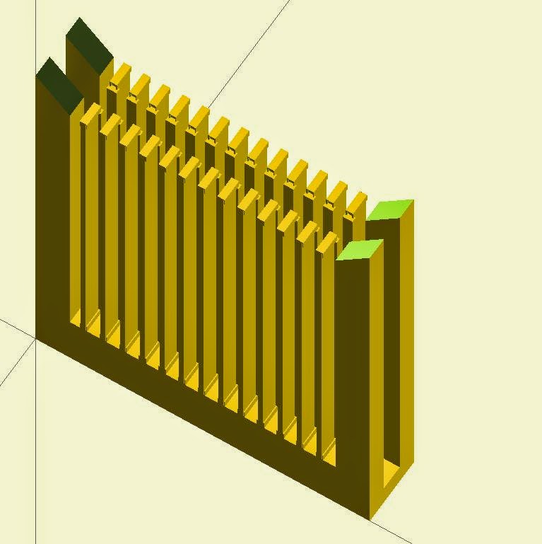
Two frames ready to be put together:
Had to put girders between the steel bars to avoid them fluxing sideways.
Had to put girders between the steel bars to avoid them fluxing sideways.
I started with re-using magnets from previous attempts and also some old ribbon speaker, but today I lost my patience and opened new boxes of magnets (the four rightmost columns):

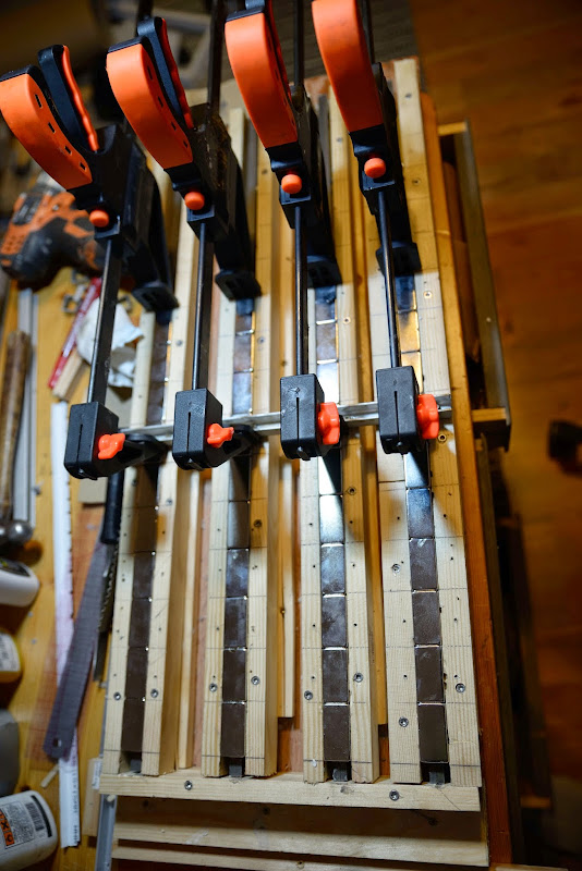
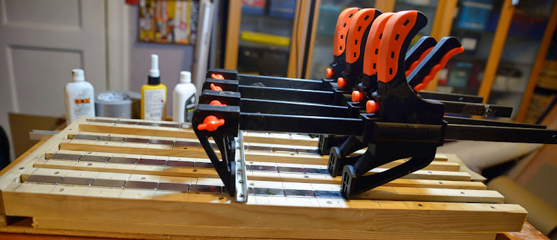
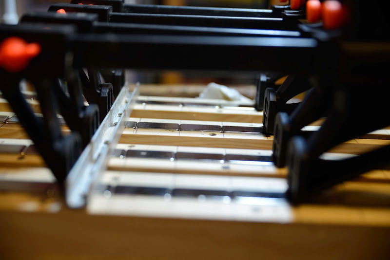
Only got within a centimeter with these clamps:
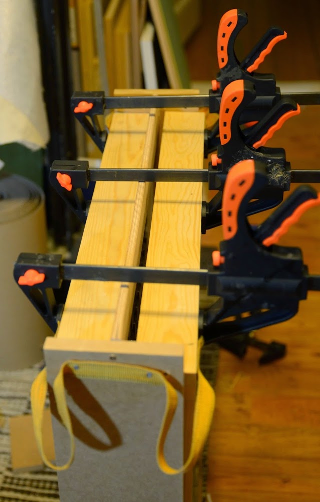
So I had to get some heavier clamps:
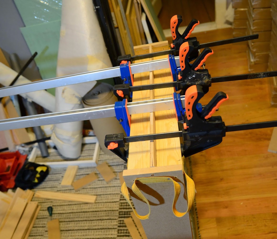
So I had to get some heavier clamps:
Last edited:
- Status
- Not open for further replies.
- Home
- Loudspeakers
- Planars & Exotics
- Yet another DIY Planar Bass