

Hello there Solhaga.
You are a brawe man 🙂
🙂
I had a plan to reuse a pair of singleended neo panels for a simular project
but chickened out 😱 but I got as long in planning that I was thinking of
using door hinges at one side for a secure (sort of) assembly.
Actually built a prototype one using ferrite magnets some 20 years ago that
played music really nice, it had some resonace problems though so I let it go.
A sinus sweep made some nasty noises, first one at 50hz and then by
multipels of that 50.
Magnets was mounted on a perforated steal sheat in the common way.
This one looks a lot more open in the magnetic assembly so maybe there want
be a problem.
Really god luck to you, I belive you are stubborn enough to pull it of so.....😀
You are a brawe man
🙂 I had a plan to reuse a pair of singleended neo panels for a simular project
but chickened out 😱 but I got as long in planning that I was thinking of
using door hinges at one side for a secure (sort of) assembly.
Actually built a prototype one using ferrite magnets some 20 years ago that
played music really nice, it had some resonace problems though so I let it go.
A sinus sweep made some nasty noises, first one at 50hz and then by
multipels of that 50.
Magnets was mounted on a perforated steal sheat in the common way.
This one looks a lot more open in the magnetic assembly so maybe there want
be a problem.
Really god luck to you, I belive you are stubborn enough to pull it of so.....😀
Thank you Dahlberg.
In fact, you see my version of your legendary Ribbon Speaker to the right in the leftmost picture above.
The magnets are now being re-used though.
I remember your idea with door hinges, but I happened to come across over 100 piano hinges at a flea market so the choice was easy.
Did you ever find out what caused the 50 Hz resonance?
Any thoughts about having a light weight, but yet stiff, membrane vs using a heavy weight one?
Thank you Dahlberg.
In fact, you see my version of your legendary Ribbon Speaker to the right in the leftmost picture above.
The magnets are now being re-used though.
I remember your idea with door hinges, but I happened to come across over 100 piano hinges at a flea market so the choice was easy.
Did you ever find out what caused the 50 Hz resonance?
Any thoughts about having a light weight, but yet stiff, membrane vs using a heavy weight one?
No I never came around to figuring out what was creating that resonace and
since I already had some single ended ones that had similar output as the
(ferrite) ribbons I laid it aside. Never really let i go either since it played
that good.
I have been using spinnaker sailcloth for bass membranes, durability is
outstanding and it ways in at 25gr/m2. It also has the benefit of only
streching in one direction, makes for a more durable bridge from membrane
to frame. You can also strech it pretty hard and still maintain a low fs.
The membrane from the resonant prototype was made from non wowen
paper, pretty high tech 20 yeas ago 🙂
Edit: Whats your maximum membrane travel ?
Last edited:
Thanks tyu.WOW....Looks great...Thanks for the pic...lot of work..hehe...or hoho.
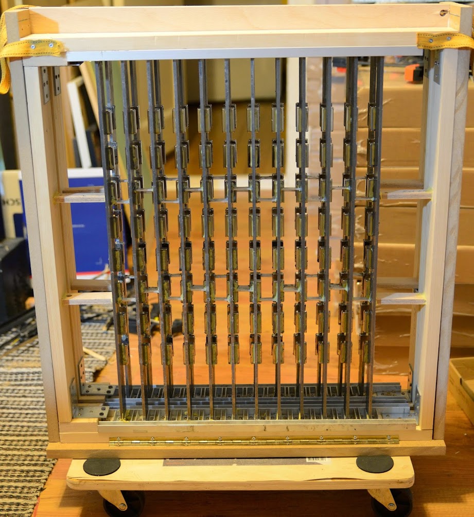
Yes, it has been a lot of work and there is much more to come.
Had to secure the top as well:

BTW, the whole thing weighs around 50 kg.
I have been using spinnaker sailcloth for bass membranes, durability is
outstanding and it ways in at 25gr/m2. It also has the benefit of only
streching in one direction, makes for a more durable bridge from membrane
to frame. You can also strech it pretty hard and still maintain a low fs.
Edit: Whats your maximum membrane travel ?
Yes, in fact we had a chat about that a couple of years ago on Hififorum.nu and a got some of the cloth back then. I think that will be my first test.
Just putting it on a frame and snap it would tell its fs, right?
Maximum travel is +/- 10 mm (gap is 20 mm). But then the membrane and coil will yield an offset in either direction so I count on at least +/- 5 mm.
I have quite an elaborate stretching frame that's a bit bigger then the actual
working frame that uses steel springs, wachers and wingnuts to create an
even tension over the full area. I have then inserted the magnetic drive system
from the back and measured fs from impedance.
Letting the working frame just keep in contact with the membrane without actually
streching it any furher gives very accurate results.
Over the first few months the fs drops a little and then stabilizes.
What happends in your femm simulations if you for instance go from 20mm to, say half of that.
5 mm travel will never ever happend, thats my experience anyway.
Yeah, I really must think a lot of this. I guess it will be a hard and cumbersome journey until I finally get it right.I have quite an elaborate stretching frame that's a bit bigger then the actual
working frame that uses steel springs, wachers and wingnuts to create an
even tension over the full area. I have then inserted the magnetic drive system
from the back and measured fs from impedance.
Letting the working frame just keep in contact with the membrane without actually
streching it any furher gives very accurate results.
One idea is to drill small holes in the main frame and then stretch the membrane like a tennis racket.
So what fs did you finally accomplish?Over the first few months the fs drops a little and then stabilizes.
Then I will chicken out! Those forces will be brutal 😱What happends in your femm simulations if you for instance go from 20mm to, say half of that.
5 mm travel will never ever happend, thats my experience anyway.
Yeah, I really must think a lot of this. I guess it will be a hard and cumbersome journey until I finally get it right.
One idea is to drill small holes in the main frame and then stretch the membrane like a tennis racket.
So what fs did you finally accomplish?
Then I will chicken out! Those forces will be brutal 😱
Fs stabilized at, if I rember it right, 18hz. It was below 20 at least.
The ribbons at 6 hz last time I measured it 😎
Brutal ? Yeahh, yes I would think so 😀
Great, then I know it will not be a lost cause to go for a light diaphragm!
I have FEMM:ed a 10 mm gap, it gives a 50 % stronger field; 0,45 T instead of 0,30 T.
I have FEMM:ed a 10 mm gap, it gives a 50 % stronger field; 0,45 T instead of 0,30 T.
Great, then I know it will not be a lost cause to go for a light diaphragm!
I have FEMM:ed a 10 mm gap, it gives a 50 % stronger field; 0,45 T instead of 0,30 T.
The sailcloth was as I remember it what gave the low fs due to its stretching abillity. I haven't tried every material available but I ended up liking the sailcloth a lot. This was for a panel that was 34x140cm. make it wider and it will go lower.
Thanks dahlberg for your valuable advice!
Do you reckon it will be enough to have tension along the sides and not on the top and bottom?
I mean, the top and bottom will be stretched anyway if the sides are stretched.
What do you think about using grommets (öljetter in Swedish) along the perimeter of the cloth in order to attach the springs (or whatever I will use)?
Thanks dahlberg for your valuable advice!
Do you reckon it will be enough to have tension along the sides and not on the top and bottom?
I mean, the top and bottom will be stretched anyway if the sides are stretched.
What do you think about using grommets (öljetter in Swedish) along the perimeter of the cloth in order to attach the springs (or whatever I will use)?
I would stretch it all around.
Maybe like a drumskin, it's what I did.
Maybe sew a channel and put a rod of some sort in it for connecting to your tennisracket analogy.
Then you may not have to attatch the membrane to the actual frame either.
The risk of buzzing from the edge of the membrane is quite big so you need
to make that connection with great precision.
First try will be with the "Icarex" PC31 ripstop polyester fabric
With 31 gr/sqm, it will only contibute with 13 grams to the complete diaphragm.
Tested it around a rod with the 3M 77-spray and it seems to hold.
The only fly in the ointment so far is that the fabric is yellow!
It will make a nice kite though should I fail.
With 31 gr/sqm, it will only contibute with 13 grams to the complete diaphragm.
Tested it around a rod with the 3M 77-spray and it seems to hold.
The only fly in the ointment so far is that the fabric is yellow!
It will make a nice kite though should I fail.
PLANAR DESIGN.!!
I would say this design is too dangerous, too complicated and too heavy, SORRY.
I would say this design is too dangerous, too complicated and too heavy, SORRY.
Sounds like Cinderella:
Oh, well. What's a royal ball? After all, I suppose it would be frightfully dull, and-and-and boring, and-and completely... Completely wonderful.
Copper wire out, aluminium foil back in
As I am now going to test a bunch of different membranes, I need a fast way of getting the coil made. Also the making of the copper wire coil tended to get a little messy.
So it is time to get the Silhouette machine back at work.
Looking at the membrane from the front a coil will be like (only half of it is shown here, each column consists of eight magnets):

An mirrored aluminium foil is placed on the back side of the membrane as well. All in all six coils for the complete 8x12 magnets.
As I am now going to test a bunch of different membranes, I need a fast way of getting the coil made. Also the making of the copper wire coil tended to get a little messy.
So it is time to get the Silhouette machine back at work.
Looking at the membrane from the front a coil will be like (only half of it is shown here, each column consists of eight magnets):
An mirrored aluminium foil is placed on the back side of the membrane as well. All in all six coils for the complete 8x12 magnets.
Last edited:
- Status
- Not open for further replies.
- Home
- Loudspeakers
- Planars & Exotics
- Yet another DIY Planar Bass