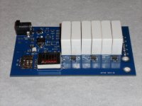
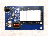
I've built a HV supply for my DIY hybrid ESLs based on a CCFL xfmr and capacitive multiplier. Runs from a 12V wall wart and produces ~3KV (adjustable). Also has a music sense circuit which can be left unpopluated and bypassed (always on or on with external switch). There is a SMT LED on the PCB to show when the circuit is active and a connector for an off board LED for same.
The PCB is 2.50" x 4.00" double sided; mixed SMT and thru hole.
If anyone is interested in building this, I can make the gerber files and BOM available. I'm not familiar with how to do a group buy, but if someone else wants to run with it, I'll do what I can to assist.
The PCB is 2.50" x 4.00" double sided; mixed SMT and thru hole.
If anyone is interested in building this, I can make the gerber files and BOM available. I'm not familiar with how to do a group buy, but if someone else wants to run with it, I'll do what I can to assist.
Attachments
... ...Vary cool setup..... thanks for posting it....just add more diodes an caps an get 5-7k Bias V....if needed....
Drop the 180meg down too................5ea 1/2watt 2meg..........youll get 3-4more db output........ helps the topend i have found in fullrang esl...
ML only set at 60meag....
Drop the 180meg down too................5ea 1/2watt 2meg..........youll get 3-4more db output........ helps the topend i have found in fullrang esl...
ML only set at 60meag....
I did 5x 18M (90MΩ) on the output so a 10MΩ DVM to ground would form a 10:1 voltage divider. If you read 315VDC on the meter, it means 3150 VDC on the output.
I didn't notice any difference in sound with different values. Of course, you are free to popluate with any values you see appropriate.
The PCB is also missing the HV connections. I've used 4-40 ¼" alum standoffs press fitted into the PCB. The HV wires have ring connectors crimped on and are then connected with 4-40 SS screws.
It might be hard to tell from the pics, but the ground pour is restricted around the HV section to prevent arcing.
Good thinkingI did 5x 18M (90MΩ) on the output so a 10MΩ DVM to ground would form a 10:1 voltage divider. If you read 315VDC on the meter, it means 3150 VDC on the output.

Overall a nicely thought out design. I did have 2 questions/ 2 comments:
Q1) Was there a reason you chose such high value capacitors? With oscillator frequency > 20kHz you could easily get by with values 100x smaller without affecting DC output voltage or ripple.
Q2) Was there a reason you have the IN terminal of the LM78L08 hooked up on the oscillator side of the C-L-C filter rather than to the IN or OUT of the LM317? As drawn, the HF noise generated by the oscillator current would be fed into the LM780L8, potentially false triggering the signal sense circuit. Perhaps it is not a concern since currents are minimal after oscillator start-up.
C1) For good common mode noise rejection in the signal sense circuit, the input capacitor pairs(C13-C18, C14-C19) need to be as tight a tolerance as the resistors.
C2) The input fuse is an excellent idea. Without it, an accidental short somewhere in the oscillator circuit could easily take out both transistors, the transformer and filter inductor.
My experience agrees with yours. If your panels are well built with minimal leakage and high resistance diaphragm coating, changing the bias resistance has no impact on the sound. In fact after diaphragm charging is complete, you should be able to completely disconnect/reconnect the supply without a listener noticing.I didn't notice any difference in sound with different values. Of course, you are free to populate with any values you see appropriate.
I agree, Nice design.
If you wanted to, it would be very easy to add a feedback circuit for regulation as well as I have done with only just a few more parts here,
http://www.diyaudio.com/forums/plan...tor-insulation-mylar-coating.html#post2848194
Does anyone have schematics of a varible HV power supply
More parts (another dual opamp), but regulation is good?!!!!
This post shows the HV regulation recovery under an arcing condition at 4.23Kv,
http://www.esldiy.com/index.php?topic=5.msg69#msg69
Cheers !!!
jer")
If you wanted to, it would be very easy to add a feedback circuit for regulation as well as I have done with only just a few more parts here,
http://www.diyaudio.com/forums/plan...tor-insulation-mylar-coating.html#post2848194
Does anyone have schematics of a varible HV power supply
More parts (another dual opamp), but regulation is good?!!!!
This post shows the HV regulation recovery under an arcing condition at 4.23Kv,
http://www.esldiy.com/index.php?topic=5.msg69#msg69
Cheers !!!
jer
Last edited:
Good thinking
Overall a nicely thought out design. I did have 2 questions/ 2 comments:
Q1) Was there a reason you chose such high value capacitors? With oscillator frequency > 20kHz you could easily get by with values 100x smaller without affecting DC output voltage or ripple.
Q2) Was there a reason you have the IN terminal of the LM78L08 hooked up on the oscillator side of the C-L-C filter rather than to the IN or OUT of the LM317? As drawn, the HF noise generated by the oscillator current would be fed into the LM780L8, potentially false triggering the signal sense circuit. Perhaps it is not a concern since currents are minimal after oscillator start-up.
C1) For good common mode noise rejection in the signal sense circuit, the input capacitor pairs(C13-C18, C14-C19) need to be as tight a tolerance as the resistors.
C2) The input fuse is an excellent idea. Without it, an accidental short somewhere in the oscillator circuit could easily take out both transistors, the transformer and filter inductor.
My experience agrees with yours. If your panels are well built with minimal leakage and high resistance diaphragm coating, changing the bias resistance has no impact on the sound. In fact after diaphragm charging is complete, you should be able to completely disconnect/reconnect the supply without a listener noticing.
Q1: I did the original design on this ~8 years ago. I may have picked the values somewhat arbitrarily.
Q2: Ditto. It may have been layout related, easier to go to the output side of the filter rather than input side, I'd have to look at the PCB plots again.
These are both good points, and could easily be changed before a GB was done. I'd welcome any other input/optimization of the circuit....
Regarding the music sense circuit: I ended up defeating the sense input on mine; the delay for the power supply to start was minimal (<1 sec) but the delay to charge the panels adequately was 10-15 secs which was quite annoying. I'd have to start the track over to hear it from the beginning. Really wasn't a big deal to flip a couple of switches when I want to listen to something.
Would these be a good alternative to Russ Knotts B3 Bias Supply? If so, I need Five of them.
I've been using two B3from Russ of justrealmusic, with the Mains from a Final Sound Surround, since he determined that the Central unit was Bad. Attempting to get three more Bias Supplies; but Russ seems quite difficult to reach...
Help, Please & Thanks
Ken
I've been using two B3from Russ of justrealmusic, with the Mains from a Final Sound Surround, since he determined that the Central unit was Bad. Attempting to get three more Bias Supplies; but Russ seems quite difficult to reach...
Help, Please & Thanks
Ken
I also would be interested in getting a few of these. My own PCB stator ESL project is moving along nicely and I would like to use adjustable supplies. I have considered using a variac in front of a simple supply like Jazzman's but the cost for the variacs alone would be about $115 each.
They look really profesional! i like the music sence part. i usually get a power suplly for a ccf tubed, the inverters kind of like the ones you see in TFT screens. and feed them wit a regulated dc and add some capacitors on the end. 3 euro for the inverterd (with tube ) and few euros for the caps. and ofc a transformer to regulate the end result.
what would boards like this coast with some more caps with lower values at the end?
) and few euros for the caps. and ofc a transformer to regulate the end result. what would boards like this coast with some more caps with lower values at the end?
Could you "write up" how each section works?
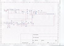
Fairly straight forward design:
T1 (a standard off the shelf CCFL supply xfmr), Q1 and Q2 form a self exciting oscillator that runs at ~50kHz if memory serves. The output of T1 drives the voltage multiplier. At 8-9VDC input, it produces ~3.3KV IIRC.
The emitter path to ground of Q1/Q2 is controlled by Q4 (music sense) or J1 (always on with on/off switch). U2B is a balanced, high gain (+33dB) AC coupled amp. The output is rectified to form a DC voltage when audio is present. Q3 switches to ground when ever music is present. R3, C12, C16, & C17 form a long time constant delay circuit to prevent the PS from shutting off between tracks or low passages. U2A inverts the output of Q3 and drives switch Q4.
There is an LED on the PCB to indicate when the HV is active and a connection for an external LED for the same purpose.
Not sure what else you would want to know?
If someone is still interested in making these, I can provide the PCB file in Eagle format, or the Gerber files in X274 format. All the parts are available from Mouser or Digikey, I can put together a BOM if necessary.
Proto boards from OshPark run about $38 per set of 3. The price won't approach anything less than that until the qty gets significantly higher.
Before anyone goes to the fab house, maybe we could all decide what changes to the layout need to be done.
Does anyone have any comments/improvements to add? My only feedback is that it would be nice to have a max voltage of something higher, perhaps 4kV. Or at least we could bump it up as much as is reasonable by adding a few steps to the multiplier.
Of course a simple switch to enable/disable the auto sense feature would be nice.
Of course a simple switch to enable/disable the auto sense feature would be nice.
Suggestions
I suggest more features
Measurement point
So when we measure the voltage between test points we know its 1000 or 10000 higher across the output.
Multiple Voltage Taps
Taps so we could use one circuit board to drive a 3 way electrostatic with 3 different bias voltages.
low voltage tap in case it is used to power DIY electrostatic headphones with "Normal Bias", (~300V) and "Pro Bias" (~750V), typical bass panels (~3-4000V), typical midrange panels (~1-2000V).
From my experiments Stax headphones would make good tweeters.
Leakage Indicator
Simple 70V neon indicator as used in Quad's High Voltage supply. I have used this in my own Stax headphone bias supply and its nice to see how often the neon blinks as it shows clearly if you have too much leakage.
It would be nice to have these indicators per panel. So paternally this should be duplicated 2X for each high voltage output tap. 2X also for the low voltage tap in case it is used to power DIY electrostatic headphones with "Normal Bias", (~300V) and "Pro Bias" (~750V), and typical bass panels (~3-4000V)
Variable output voltage
So with a potentiality we can adjust the output voltage approximately +-50%, using a simple potentiometer. (Maybe already in the deisgn?)
Useful when building your own pannels.
This is also useful for making pannels work that are partially damaged when you dont have time to fix them until Sunday or so.
I suggest more features
- Measurement point
- Multiple Voltage Taps
- Leakage Indicator
- Variable output voltage
Measurement point
So when we measure the voltage between test points we know its 1000 or 10000 higher across the output.
Multiple Voltage Taps
Taps so we could use one circuit board to drive a 3 way electrostatic with 3 different bias voltages.
low voltage tap in case it is used to power DIY electrostatic headphones with "Normal Bias", (~300V) and "Pro Bias" (~750V), typical bass panels (~3-4000V), typical midrange panels (~1-2000V).
From my experiments Stax headphones would make good tweeters.
Leakage Indicator
Simple 70V neon indicator as used in Quad's High Voltage supply. I have used this in my own Stax headphone bias supply and its nice to see how often the neon blinks as it shows clearly if you have too much leakage.
It would be nice to have these indicators per panel. So paternally this should be duplicated 2X for each high voltage output tap. 2X also for the low voltage tap in case it is used to power DIY electrostatic headphones with "Normal Bias", (~300V) and "Pro Bias" (~750V), and typical bass panels (~3-4000V)
Variable output voltage
So with a potentiality we can adjust the output voltage approximately +-50%, using a simple potentiometer. (Maybe already in the deisgn?)
Useful when building your own pannels.
This is also useful for making pannels work that are partially damaged when you dont have time to fix them until Sunday or so.
Last edited:
Regarding the measurement point: It has that ability now with the 5x 18M resistors. Connecting a 10M DVM to ground forms a 10:1 voltage divider so you can read the output on a 400V setting. Best to make the connection before applying power as there will be 3KV present until the circuit is complete and you could end up frying your meter. Maybe an AC voltage measurement at the output of the CCFL xfmr would be better?
Multiple voltage taps: Possible, but a better than 10:1 range might not be practical. Probably best to draw up a schematic of the multiplier with the taps you would want. I can see what it does to the PCB layout from there.
Leakage indicator: Ditto on the schematic.
Variable voltage: As drawn, the variable regulator in the front end does accomplish this somewhat, but not ±50%. I think Geraldfryjr had a very nice regulated design, but that may be beyond what this project is intended as.
If the group can come up with a (reasonable) schematic of what you would want, I'll do the CAD work to make it a group buy.
Thanks Pyramid I know I was asking for the kitchen sink
But what better way to get the ball rolling
Neon indicator would just go parrarllel with R8 on your schematic.
The daisy chained Resistors like your R4 - R8 should be duplicated per pannel.
Multiple tap points from your diode ladder would be from the different points on the ladder.
Thats how I woudl think you could do most of this
Shame we cant get ±50%.
Best regards
Thanks Pyramid I know I was asking for the kitchen sink
But what better way to get the ball rolling
Neon indicator would just go parrarllel with R8 on your schematic.
The daisy chained Resistors like your R4 - R8 should be duplicated per pannel.
Multiple tap points from your diode ladder would be from the different points on the ladder.
Thats how I woudl think you could do most of this
Shame we cant get ±50%.
Best regards
Got it. FYI, these were designed to be one PCB per channel (panel). They are powered by a 9V 300mA DC output wall adapter, with one powering each speaker.
Of course a simple switch to enable/disable the auto sense feature would be nice.
Not difficult to add; just parallel the jumper across Q4. If the jumper is in, PS is running all the time (subject to external power switch). If out, it only runs when music is sensed.
So can we summarize what it is that we think should be changed? Maybe a list that is realistic and sensible? After all, if we make this too complicated it will increase the cost and turn off newcomers. I think that the most common users are interested in a relatively cheap supply that can run up to at least 4kV (anthonybisset suggests 6, which seems to be fine). So maybe we add a higher max voltage to the wish list.
The features that will drive people to use this are the audio sense power-on and the adjustable voltage.
Test points for measuring 1/10 or 1/20 of the output voltage is also quite nice. Every user should verify the bias voltage and very few people want to spend $200 USD for HV probe for their DMM.
The features that will drive people to use this are the audio sense power-on and the adjustable voltage.
Test points for measuring 1/10 or 1/20 of the output voltage is also quite nice. Every user should verify the bias voltage and very few people want to spend $200 USD for HV probe for their DMM.
Regulation!!
I have already provided a means of such enhancements in post 5.
The only thing I didn't do was employ a automatic turn on and delayed turn off circuit.
I would limit the highest voltage setting to about 7kv or 7.5kv or less for the average DIY'er.
Above that you are superseding the limitation of common DIY'er materials and transformer insulation materials.
FWIW
Cheers!!
jer
Last edited:
- Status
- This old topic is closed. If you want to reopen this topic, contact a moderator using the "Report Post" button.
- Home
- Loudspeakers
- Planars & Exotics
- ESL High Voltage supply